Multiple Choice
A galvanometer G has an internal resistance rg. A VOLTMETER is constructed by incorporating the galvanometer and an additional resistance Rs. Which one of the figures below is the most appropriate circuit diagram for the voltmeter? 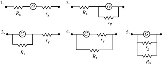
A) 1
B) 2
C) 3
D) 4
E) 5
Correct Answer:

Verified
Correct Answer:
Verified
Q5: A 5.0-Ω resistor and a 9.0-Ω resistor
Q14: A 4.0-μF capacitor that is initially uncharged
Q29: A light bulb is connected in the
Q30: Consider the circuit shown in the figure.
Q32: Two identical resistors of resistance R =
Q33: As more resistors are added in parallel
Q35: Three resistors are connected across an ideal
Q36: A galvanometer G has an internal resistance
Q37: An uncharged 1.0-μF capacitor is connected in
Q38: The figure shows three identical lightbulbs connected