Short Answer
For the circuit shown in the figure, , , and the batteries are ideal. Determine and .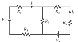
Correct Answer:

Verified
Correct Answer:
Verified
Related Questions
Q268: Three resistors with resistances of
Q269: For the circuit shown in the
Q270: A network of capacitors is mostly
Q271: For the circuit shown in the
Q272: A <span class="ql-formula" data-value="20.0 -
Q274: The inductance of a solenoid that
Q275: In the circuit shown in the
Q276: A series ac circuit has a
Q277: The network shown is assembled with
Q278: A transformer is a device used to<br>A)