Multiple Choice
For the circuit shown in the figure, , and the battery is ideal. Initially the switch is open and the capacitor is uncharged. The switch is then closed at time . What is the potential difference across the resistor after closing the switch?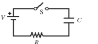
A)
B)
C)
D)
E)
Correct Answer:

Verified
Correct Answer:
Verified
Related Questions
Q264: A series circuit containing an inductor
Q265: The area of a rectangular loop
Q266: In the figure, which of the
Q267: A <span class="ql-formula" data-value="10 -
Q268: Three resistors with resistances of
Q270: A network of capacitors is mostly
Q271: For the circuit shown in the
Q272: A <span class="ql-formula" data-value="20.0 -
Q273: For the circuit shown in the
Q274: The inductance of a solenoid that