Multiple Choice
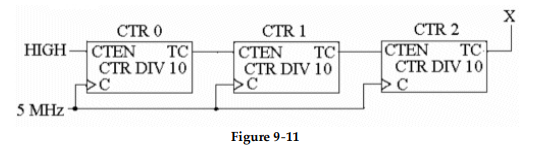
-The circuit in Figure 9- 11 is used for _________ and for the inputs shown, the DATA OUT will be _________ .
A) parallel- to- serial conversion, HIGH
B) demultiplexing, 0
C) multiplexing, 1
D) parallel- to- serial conversion, 0
Correct Answer:

Verified
Correct Answer:
Verified
Q40: Which of the following statements best describes
Q41: <img src="https://d2lvgg3v3hfg70.cloudfront.net/TB9838/.jpg" alt=" -Which
Q42: <img src="https://d2lvgg3v3hfg70.cloudfront.net/TB9838/.jpg" alt=" -The
Q43: <img src="https://d2lvgg3v3hfg70.cloudfront.net/TB9838/.jpg" alt=" -During
Q44: <img src="https://d2lvgg3v3hfg70.cloudfront.net/TB9838/.jpg" alt=" -If
Q45: In many cases, counters must be strobed
Q46: <img src="https://d2lvgg3v3hfg70.cloudfront.net/TB9838/.jpg" alt=" -What
Q47: <img src="https://d2lvgg3v3hfg70.cloudfront.net/TB9838/.jpg" alt=" -What
Q48: <img src="https://d2lvgg3v3hfg70.cloudfront.net/TB9838/.jpg" alt=" -The
Q49: <img src="https://d2lvgg3v3hfg70.cloudfront.net/TB9838/.jpg" alt=" -Refer