Multiple Choice
The timing diagram below is correct for a 2- input _________ gate.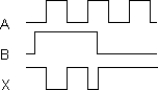
A) AND
B) OR
C) NAND
D) Exclusive-OR
Correct Answer:

Verified
Correct Answer:
Verified
Related Questions
Q37: The output of an OR gate is
Q38: HDLs differ from_ in that they include
Q39: The_in a VHDL program describes its logic
Q40: The symbol below represents a(n)_<br><img src="https://d2lvgg3v3hfg70.cloudfront.net/TB9838/.jpg" alt="The
Q41: The output of a 2- input Exclusive-
Q43: Which type of gate can be used
Q44: A LOW input to an inverter produces
Q45: The_in a VHDL program defines the logic
Q46: The timing diagram below is correct for
Q47: When an open occurs on the input