Essay
In the circuit of Fig. 11.7.1 (refer to Figure below), assume that coupling capacitors and are very large and thus act as perfect short circuits at
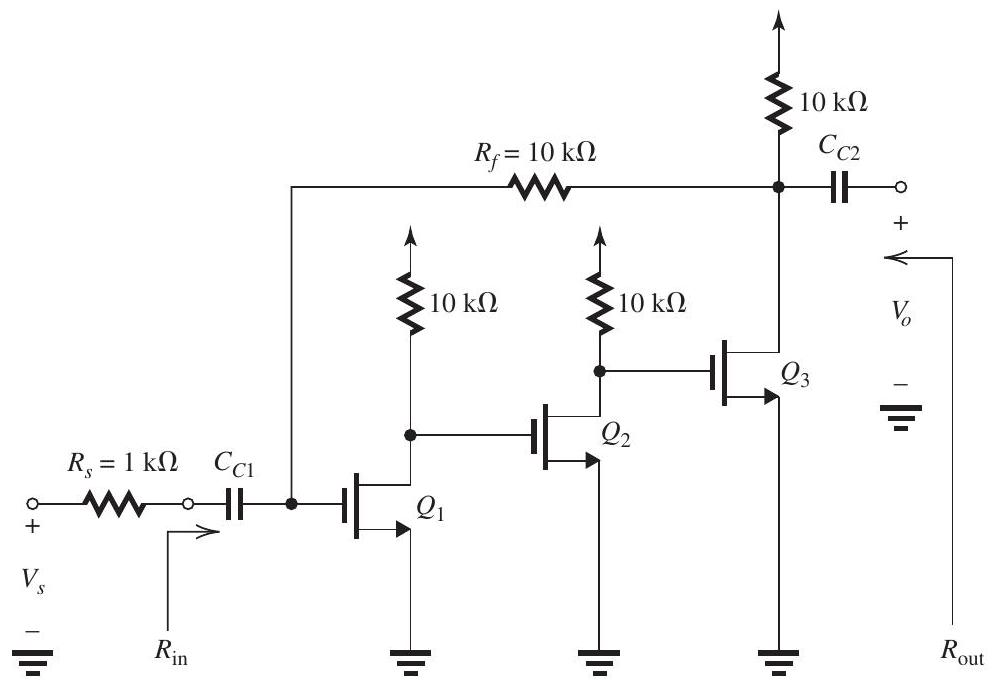
Figure 11.7.1
the frequencies of interest. Transistors , and are identical and are operating at identical dc bias conditions so that each has and .
(a) Replacing the signal source and with its Norton's equivalent circuit, show that this feedback amplifier utilizes the shunt-shunt feedback topology.
(b) Give the circuit and determine the value of .
(c) Give the ideal value of the closed-loop gain and hence of the voltage gain .
(d) Provide the circuit and determine the values of , and .
(e) Find the values of , and .
(f) Find the actual value of voltage gain realized and compare to the approximate value found in (c).
(g) Find the value of ,
(h) Find the value of .
(i) If is , find the magnitudes of the signals at the gates of , and and at the output (i.e., ).
Correct Answer:

Verified
Correct Answer:
Verified
Q1: Figure 11.6.1 (refer to Figure below)<br>
Q2: <img src="https://d2lvgg3v3hfg70.cloudfront.net/TBO1243/.jpg" alt="
Q3: <img src="https://d2lvgg3v3hfg70.cloudfront.net/TBO1243/.jpg" alt="
Q4: <img src="https://d2lvgg3v3hfg70.cloudfront.net/TBO1243/.jpg" alt="
Q5: <img src="https://d2lvgg3v3hfg70.cloudfront.net/TBO1243/.jpg" alt="
Q6: An amplifier with an open-loop gain
Q7: The feedback voltage amplifier in Fig.
Q9: <img src="https://d2lvgg3v3hfg70.cloudfront.net/TBO1243/.jpg" alt="