Essay
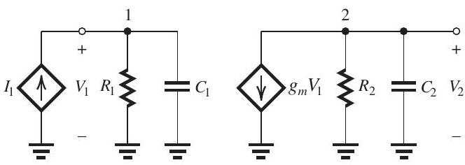
Figure 11.9.1
An op amp has a dc gain of and three real-axis poles with frequencies , , and . The op-amp internal circuit includes an amplifier stage having the equivalent circuit shown in Fig. 11.9.1, where , and . Furthermore, it is found that the input circuit of this stage is responsible for the pole at and that the output circuit is responsible for the pole at . It is required to frequency-compensate this op amp so that it becomes stable in closed-loop configurations with a closed-loop gain as low as unity.
(a) Sketch and clearly label a Bode plot for the op amp gain. Use a frequency axis that extends from to .
(b) If the frequency compensation is achieved by connecting a capacitor in parallel with , find the required value of and sketch the modified gain response on your Bode plot.
(c) If the frequency compensation is achieved by placing a capacitor in the feedback path of the amplifier stage in Fig. 11.9.1 -that is, between nodes 1 and 2 (Miller compensation)-find the required value of . Also, find the new frequencies of the poles and sketch the modified gain on your Bode plot.
Correct Answer:

Verified

(a) See Fig. 11.9.2.
(b)
\[\begin{al ...View Answer
Unlock this answer now
Get Access to more Verified Answers free of charge
Correct Answer:
Verified
(a) See Fig. 11.9.2.
(b)
\[\begin{al ...
View Answer
Unlock this answer now
Get Access to more Verified Answers free of charge
Q1: Figure 11.6.1 (refer to Figure below)<br>
Q2: <img src="https://d2lvgg3v3hfg70.cloudfront.net/TBO1243/.jpg" alt="
Q3: <img src="https://d2lvgg3v3hfg70.cloudfront.net/TBO1243/.jpg" alt="
Q4: <img src="https://d2lvgg3v3hfg70.cloudfront.net/TBO1243/.jpg" alt="
Q6: An amplifier with an open-loop gain
Q7: The feedback voltage amplifier in Fig.
Q8: In the circuit of Fig. 11.7.1
Q9: <img src="https://d2lvgg3v3hfg70.cloudfront.net/TBO1243/.jpg" alt="