Essay
Consider the single-line diagram of the power system shown in Figure P3.11. Equipment rating are:}
Neglecting resistance, transformer phase shift, and magnetizing reactance, draw the equivalent reactance diagram. Use a base of and for the 40 -ohm line. Determine the per-unit reactances.
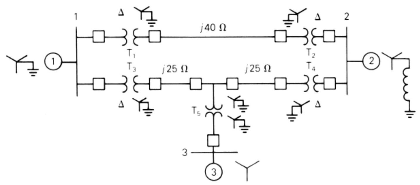
FIGURE P3.11
Correct Answer:

Verified

Per unit positive sequence r...View Answer
Unlock this answer now
Get Access to more Verified Answers free of charge
Correct Answer:
Verified
Per unit positive sequence r...
View Answer
Unlock this answer now
Get Access to more Verified Answers free of charge
Q7: The ratings of a three-phase three-winding
Q8: A single-phase three-winding transformer has the
Q9: Consider a bank of three single-phase
Q10: A single-phase <span class="ql-formula" data-value="100-\mathrm{kVA},
Q11: For a conceptual single-phase, phase-shifting transformer,
Q13: Figure P3.15 shows a one-line diagram
Q14: Three single-phase transformers, each rated
Q15: A 100-MVA, 13.2-kV three-phase generator, which
Q16: A balanced Y-connected voltage source with
Q17: Using the transformer ratings as base quantities,