menu-iconExamlexExamLexServices

Discover

Ask a Question
  1. All Topics
  2. Topic
    Engineering
  3. Study Set
    Electronic Principles
  4. Exam
    Exam 7: BJT Biasing
  5. Question
    The Emitter Current in the Circuit Shown in Figure 7-12
Solved

The Emitter Current in the Circuit Shown in Figure 7-12

Question 41

Question 41

True/False

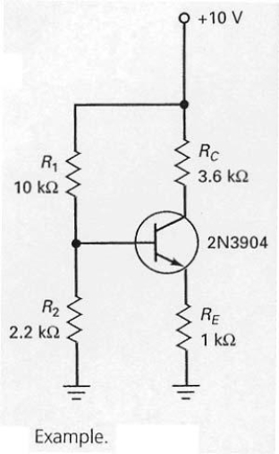
The emitter current in the circuit shown in Figure 7-12 can be calculated by dividing +10 V by 1 kW.

Correct Answer:

verifed

Verified

Unlock this answer now
Get Access to more Verified Answers free of charge

Related Questions

Q36: The most widely used transistor biasing circuit

Q37: The main advantage of an optocoupler is<br>A)

Q38: With a pnp transistor,the base-emitter junction will

Q39: By exposing a transistor's collector junction to

Q40: In the circuit shown in Figure 7-26,if

Q42: In Figure 7-18,the negative supply <img src="https://d2lvgg3v3hfg70.cloudfront.net/TB4790/.jpg"

Q43: In Figure 7-5,if the fuse blows open

Q44: With the values shown at the operating

Q45: The schematic diagram of a pnp transistor

Q46: In order to calculate the base voltage

Examlex

ExamLex

About UsContact UsPerks CenterHomeschoolingTest Prep

Work With Us

Campus RepresentativeInfluencers

Links

FaqPricingChrome Extension

Download The App

Get App StoreGet Google Play

Policies

Privacy PolicyTerms of ServiceHonor CodeCommunity Guidelines

Scan To Download

qr-code

Copyright © (2025) ExamLex LLC.

Privacy PolicyTerms Of ServiceHonor CodeCommunity Guidelines