Multiple Choice
In the circuit shown in Figure 7-26,if the base voltage measured 0 V and the emitter voltage measured 0 V,what should the troubleshooter do? 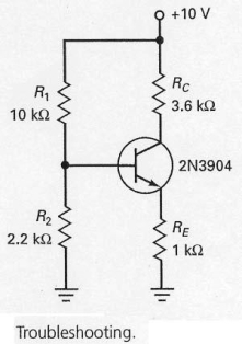
A) replace the transistor
B) replace RE
C) check R1
D) check voltage source and leads
Correct Answer:

Verified
Correct Answer:
Verified
Q35: Emitter-feedback bias uses a resistor that provides
Q36: The most widely used transistor biasing circuit
Q37: The main advantage of an optocoupler is<br>A)
Q38: With a pnp transistor,the base-emitter junction will
Q39: By exposing a transistor's collector junction to
Q41: The emitter current in the circuit shown
Q42: In Figure 7-18,the negative supply <img src="https://d2lvgg3v3hfg70.cloudfront.net/TB4790/.jpg"
Q43: In Figure 7-5,if the fuse blows open
Q44: With the values shown at the operating
Q45: The schematic diagram of a pnp transistor