Multiple Choice
While troubleshooting the circuit shown in Figure 7-26,the base voltage measures 1.8 V and the collector voltage measures 10 V,what should the technician do? 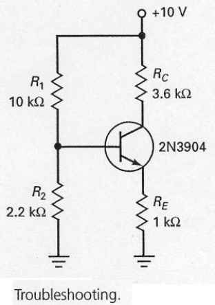
A) replace the transistor
B) replace RE
C) check R1
D) check voltage source and leads
Correct Answer:

Verified
Correct Answer:
Verified
Q1: In order to determine the emitter current
Q3: To prevent meter loading,a voltmeter used to
Q4: In the circuit shown in Figure 7-26,if
Q5: Whenever you have a circuit with npn
Q6: Collector-feedback bias is still sensitive to changes
Q7: Voltage-divider bias is really emitter bias in
Q8: The intent of emitter-feedback bias is to<br>A)
Q9: Collector-feedback bias is also called<br>A) self-bias.<br>B) collector
Q10: Once the base voltage has been calculated
Q11: With the switch in the position as