Multiple Choice
Once the base voltage has been calculated for the circuit shown in Figure 7-29 (b) ,emitter voltage can be calculated by 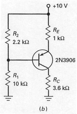
A) adding 0.7 V to the base voltage.
B) subtracting 0.7 V from the base voltage.
C) adding 0.3 V to the base voltage.
D) subtracting 0.3 V from the base voltage.
Correct Answer:

Verified
Correct Answer:
Verified
Q5: Whenever you have a circuit with npn
Q6: Collector-feedback bias is still sensitive to changes
Q7: Voltage-divider bias is really emitter bias in
Q8: The intent of emitter-feedback bias is to<br>A)
Q9: Collector-feedback bias is also called<br>A) self-bias.<br>B) collector
Q11: With the switch in the position as
Q12: Since voltage-divider bias is derived from emitter
Q13: In Figure 7-21,what effect do the capacitors
Q14: The biasing configuration shown in Figure 7-18
Q15: If R<sub>E</sub> is adjusted to its maximum