Multiple Choice
The biasing configuration shown in Figure 7-18 is derived from emitter bias and is referred to as 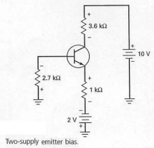
A) emitter derived bias (EDB) .
B) bi-polar emitter bias (BPEB) .
C) two-supply emitter bias (TSEB) .
D) one-supply emitter bias (OSEB) .
Correct Answer:

Verified
Correct Answer:
Verified
Q9: Collector-feedback bias is also called<br>A) self-bias.<br>B) collector
Q10: Once the base voltage has been calculated
Q11: With the switch in the position as
Q12: Since voltage-divider bias is derived from emitter
Q13: In Figure 7-21,what effect do the capacitors
Q15: If R<sub>E</sub> is adjusted to its maximum
Q16: What should a troubleshooter do if the
Q17: Using a firm voltage divider means that
Q18: With ambiguous troubles,the troubleshooter very often must<br>A)
Q19: A well-designed voltage-divider bias circuit is one