Multiple Choice
The network shown in the figure is assembled with uncharged capacitors X, Y, and Z, with CX = 7.0 μF, CY = 7.0 μF, and CZ = 6.0 μF, and open switches, S1 and S2. A potential difference Vab = +120 V is applied between points a and b. After the network is assembled, switch S1 is closed for a long time, but switch S2 is kept open. Then switch S1 is opened and switch S2 is closed. What is the final voltage across capacitor X? 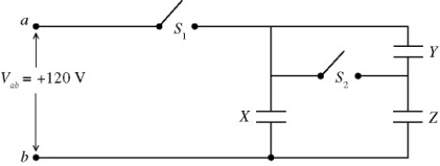
A) 94 V
B) 87 V
C) 79 V
D) 71 V
E) 63 V
Correct Answer:

Verified
Correct Answer:
Verified
Q1: Three capacitors are connected as shown in
Q2: A charge of 2.00 μC flows onto
Q4: Equal but opposite charges Q are placed
Q4: An ideal air-filled parallel-plate capacitor has round
Q5: In the circuit shown in the figure,
Q6: An ideal parallel-plate capacitor consists of a
Q7: A parallel-plate capacitor with plate separation of
Q8: The capacitive network shown in the figure
Q11: Five capacitors are connected across a potential
Q52: A 1.0-μF and a 2.0-μF capacitor are