Exam 12: Rl Circuits
Exam 1: Quantities and Units31 Questions
Exam 2: Voltage, Current, and Resistance69 Questions
Exam 3: Ohms Law, Energy, and Power64 Questions
Exam 4: Series Circuits64 Questions
Exam 5: Parallel Circuits62 Questions
Exam 6: Series-Parallel Circuits71 Questions
Exam 7: Magnetism and Electromagnetism66 Questions
Exam 8: Introduction to Alternating Current and Voltage66 Questions
Exam 9: Capacitors66 Questions
Exam 10: Rc Circuits65 Questions
Exam 11: Inductors62 Questions
Exam 12: Rl Circuits64 Questions
Exam 13: Rlc Circuits and Resonance68 Questions
Exam 14: Time Response of Reactive Circuits65 Questions
Exam 15: Transformers65 Questions
Exam 16: Regulators, Filters, and Op-Amps307 Questions
Exam 17: Understanding Transducers, Sensors, and Conversion in Industrial Processes80 Questions
Select questions type
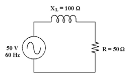 -If the frequency increases in Figure 12-1, the phase angle ________ and the impedance ________.
Free
(Multiple Choice)
4.8/5  (35)
(35)
Correct Answer: Verified
D
In an RL filter circuit, the cutoff frequency is defined as the frequency at Which:
Free
(Multiple Choice)
4.8/5 (43)
Correct Answer:Verified
B
-What is the cut off frequency in Figure 12-1?
Free
(Multiple Choice)
4.9/5 (33)
Correct Answer:Verified
A
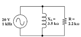 -If the resistor decreases in Figure 12-2, the total current ________.
(Multiple Choice)
4.8/5 (33)
-If the resistance increases in Figure 12-2, the total current ________.
(Multiple Choice)
4.9/5 (44)
If a high-pass RL filterʹs cutoff frequency is 55 kHz, its bandwidth is theoretically ________.
(Multiple Choice)
4.8/5 (33)
The source voltage always leads the total current in an RL circuit.
(True/False)
4.8/5 (39)
-If the frequency increases in Figure 12-1, inductance ________.
(Multiple Choice)
4.7/5 (28)
Power dissipated by the resistor in a parallel RL circuit can be increased With the addition of a capacitor in parallel.
(True/False)
4.8/5 (34)
If a low-pass RL filterʹs cutoff frequency is 20 kHz, its bandwidth is ________.
(Multiple Choice)
4.8/5 (36)
The impedance of a series RL circuit is found by adding the values of XL and R using a phasor diagram.
(True/False)
4.7/5 (35)
If a load is purely inductive and the reactive power is 10 VAR, the apparent power is ________.
(Multiple Choice)
4.8/5 (30)
In a series RL circuit, as the phase angle between the applied voltage and the total current increases, this is the same as:
(Multiple Choice)
4.9/5 (28)
If the true power is 10W and the reactive power is 10 VAR, the apparent power is ________.
(Multiple Choice)
4.9/5 (31)
-If the operating frequency decreases in Figure 12-1, the current ________.
(Multiple Choice)
4.8/5 (33)
An ohmmeter can be used to accurately test the impedance of an RL circuit.
(True/False)
4.9/5 (37)
-What change Would increase the power factor in Figure 12-2?
(Multiple Choice)
4.9/5 (29)
The overall phase angle of a parallel circuit with a resistance of 20 and an inductive reactance of 25 would be nearly 90 degrees.
(True/False)
4.9/5 (43)
Filters
- Essay(0)
- Multiple Choice(0)
- Short Answer(0)
- True False(0)
- Matching(0)