Exam 29: Alternating-Current Circuits
Exam 1: Systems of Measurement86 Questions
Exam 2: Motion in One Dimension83 Questions
Exam 3: Motion in Two and Three Dimensions60 Questions
Exam 4: Newtons Laws106 Questions
Exam 5: Applications of Newtons Laws73 Questions
Exam 6: Work and Energy60 Questions
Exam 7: Conservation of Energy56 Questions
Exam 8: Systems of Particles and Conservation of Linear Momentum92 Questions
Exam 9: Rotation105 Questions
Exam 10: Conservation of Angular Momentum66 Questions
Exam 11: Gravity84 Questions
Exam 12: Static Equilibrium and Elasticity58 Questions
Exam 13: Fluids77 Questions
Exam 14: Oscillations126 Questions
Exam 15: Wave Motion112 Questions
Exam 16: Superposition and Standing Waves87 Questions
Exam 17: Temperature and the Kinetic Theory of Gases78 Questions
Exam 18: Heat and the First Law of Thermodynamics100 Questions
Exam 19: The Second Law of Thermodynamics59 Questions
Exam 20: Thermal Properties and Processes50 Questions
Exam 21: The Electric Field I: Discrete Charge Distributions55 Questions
Exam 22: The Electric Field Ii: Continuous Charge Distributions64 Questions
Exam 23: Electric Potential87 Questions
Exam 24: Capacitance63 Questions
Exam 25: Electric Current and Direct-Current Circuits107 Questions
Exam 26: The Magnetic Field33 Questions
Exam 27: Sources of the Magnetic Field86 Questions
Exam 28: Magnetic Induction56 Questions
Exam 29: Alternating-Current Circuits106 Questions
Exam 30: Maxwells Equations and Electromagnetic Waves57 Questions
Exam 31: Properties of Light82 Questions
Exam 32: Optical Images106 Questions
Exam 33: Interference and Diffraction91 Questions
Exam 34: Wave Particle Duality and Quantum Physics140 Questions
Exam 35: Applications of the Schrodinger Equation42 Questions
Exam 36: Atoms113 Questions
Exam 37: Molecules39 Questions
Exam 38: Solids and the Theory of Conduction75 Questions
Exam 39: Relativity82 Questions
Exam 40: Nuclear Physics107 Questions
Exam 41: Elementary Particles and the Beginning of the Universe68 Questions
Select questions type
A circuit contains a capacitor (C F),an inductor (L mH),and an ohmic resistor (R )connected in series.If you change the potential across this series combination,the values that change (if you neglect thermal effects)are
(Multiple Choice)
4.9/5  (32)
(32)
Use the following figure for the next problem. 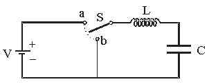 The battery has a voltage V = 6 V, the inductance of the inductor L = 12 mH and the capacitance of the capacitor
  Assume that the inductor and the wires have zero resistance.
-The switch S was at position a for a long time when it is switched to b.Describe the current flow in the right loop.
Assume that the inductor and the wires have zero resistance.
-The switch S was at position a for a long time when it is switched to b.Describe the current flow in the right loop.
(Multiple Choice)
4.7/5 (35)
You connect a 100- resistor,a 800-mH inductor,and a 10.0- F capacitor in series across a 60.0-Hz,120-V (peak)source.The impedance of your circuit is approximately
(Multiple Choice)
4.8/5 (35)
Use the following figure for the next problem.
The battery has a voltage V = 6 V, the inductance of the inductor L = 12 mH and the capacitance of the capacitor Assume that the inductor and the wires have zero resistance.
-The switch S was at position a for a long time when it is switched to b.What is the charge on the capacitor at t = 0 s?
(Multiple Choice)
4.8/5 (39)
A series RLC circuit is driven by a 1.0-kHz oscillator.The circuit parameters are Vrms = 12 V,L = 5.0 mH,C = 4.0 F,and R = 10 .Under steady-state conditions,the rms current in the circuit will be
(Multiple Choice)
4.9/5 (35)
You connect a 250- resistor,a 1.20-mH inductor,and a 1.80- F capacitor in series across a 60.0-Hz,120-V (peak)source.When you connect a voltmeter across the capacitor in this circuit,the meter reads approximately
(Multiple Choice)
4.9/5 (37)
A series RLC circuit is driven by a 1.0-kHz oscillator.The circuit parameters are L = 5.0 mH,C = 4.0 F,R = 10 .What is the impedance of this circuit?
(Multiple Choice)
4.7/5 (31)
How much does the maximum EMF produced by a generator (a rotating coil)change if the number of turns of the coil is tripled?
(Multiple Choice)
4.9/5 (36)
At what frequency would the reactance of a 1.0-mH inductor be twice that of a 10- F capacitor?
(Multiple Choice)
4.9/5 (33)
Two heaters are plugged into the same 120-V AC outlet.If one heater is rated at 1100 W,then what can be the maximum rating of the second heater in order not to exceed the 20 A trip rating on the circuit?
(Multiple Choice)
4.9/5 (34)
Use the following figure for the next problem. 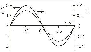 -The figure shows the voltage and current for a device.The frequency of the voltage is
(Multiple Choice)
4.9/5 (35)
Use the following figure for the next problem.
The battery has a voltage V = 6 V, the inductance of the inductor L = 12 mH and the capacitance of the capacitor Assume that the inductor and the wires have zero resistance.
-The switch S was at position a for a long time when it is switched to b. What is the charge on the capacitor at t = 0.487 ms?
(Multiple Choice)
4.8/5 (39)
A 5-µF capacitor is charged to 30 V and is then connected across a 10-µH inductor.The frequency of oscillation of the energy stored in the electric field of the capacitor and the magnetic field of the inductor is
(Multiple Choice)
4.9/5 (35)
A 10-mH inductor has an internal resistance of 10 .The impedance of this inductor for a frequency of 60 Hz is approximately
(Multiple Choice)
4.8/5 (39)
If you were to plug a 1200-W heater and a 600-W toaster into a 110-V electrical outlet,what total rms current would these two appliances draw if the wiring is parallel?
(Multiple Choice)
4.8/5 (43)
At what frequency is the reactance of a 2-mH inductor equal to the reactance of a 100-pF capacitor?
(Multiple Choice)
4.9/5 (37)
Use the following figure to answer the next problem: 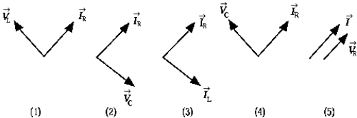 -The diagram that correctly represents the phase relationship between the current through the resistor and the voltage ACross the capACitor in a circuit containing an inductor L,a capACitor C,and a resistor R all connected in series is
(Multiple Choice)
4.9/5 (37)
You connect a 250- resistor,a 1.20-mH inductor,and a 1.80- F capacitor in series across a 60.0-Hz,120-V (peak)source.When you connect a voltmeter across the resistor in this circuit,the meter reads approximately
(Multiple Choice)
4.8/5 (35)
You connect a 250- resistor,a 1.20-mH inductor,and a 1.80- F capacitor in series across a 60.0-Hz,120-V (peak)source.When you connect a voltmeter across the inductor in this circuit,the meter reads approximately
(Multiple Choice)
4.9/5 (33)
Filters
- Essay(0)
- Multiple Choice(0)
- Short Answer(0)
- True False(0)
- Matching(0)