Multiple Choice
In the circuit shown in Figure 7-29 (a) ,the base voltage can be calculated by 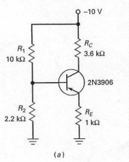
A) using the voltage divider rule using R1 and R2 and the supply voltage.
B) using the voltage divider rule using RC and RE and the supply voltage.
C) multiplying collector current by the collector resistor.
D) multiplying emitter current by the emitter resistor.
Correct Answer:

Verified
Correct Answer:
Verified
Q40: In the circuit shown in Figure 7-26,if
Q41: The emitter current in the circuit shown
Q42: In Figure 7-18,the negative supply <img src="https://d2lvgg3v3hfg70.cloudfront.net/TB4790/.jpg"
Q43: In Figure 7-5,if the fuse blows open
Q44: With the values shown at the operating
Q45: The schematic diagram of a pnp transistor
Q46: In order to calculate the base voltage
Q47: A well-designed voltage-divider bias circuit is one
Q49: A firm voltage divider means that the
Q50: Voltage-divider bias produces a fixed value of