Exam 27: Circuits
Exam 1: Measurement37 Questions
Exam 2: Motion Along a Straight Line90 Questions
Exam 3: Vector32 Questions
Exam 4: Motion in Two and Three Dimensions53 Questions
Exam 5: Force and Motion I73 Questions
Exam 6: Force and Motion II74 Questions
Exam 7: Kinetic Energy and Work72 Questions
Exam 8: Potential Energy and Conservation of Energy62 Questions
Exam 9: Center of Mass and Linear Momentum98 Questions
Exam 10: Rotation99 Questions
Exam 11: Rolling, Torque, and Angular Momentum65 Questions
Exam 12: Equilibrium and Elasticity57 Questions
Exam 13: Gravitation54 Questions
Exam 14: Fluids87 Questions
Exam 15: Oscillations75 Questions
Exam 16: Waves I80 Questions
Exam 17: Waves II70 Questions
Exam 18: Temperature, Heat, and the First Law of Thermodynamics96 Questions
Exam 19: The Kinetic Theory of Gases111 Questions
Exam 20: Entropy and the Second Law of Thermodynamics61 Questions
Exam 21: Electric Charge51 Questions
Exam 22: Electric Fields52 Questions
Exam 23: Gauss Law39 Questions
Exam 24: Electric Potential50 Questions
Exam 25: Capacitance59 Questions
Exam 26: Current and Resistance54 Questions
Exam 27: Circuits73 Questions
Exam 28: Magnetic Fields51 Questions
Exam 29: Magnetic Fields Due to Currents48 Questions
Exam 30: Induction and Inductance90 Questions
Exam 31: Electromagnetic Oscillations and Alternating Current86 Questions
Exam 32: Maxwells Equations; Magnetism of Matter81 Questions
Exam 33: Electromagnetic Waves81 Questions
Exam 34: Images78 Questions
Exam 35: Interference45 Questions
Exam 36: Diffraction77 Questions
Exam 37: Relativity68 Questions
Exam 38: Photons and Matter Waves57 Questions
Exam 39: More About Matter Waves41 Questions
Exam 40: All About Atoms76 Questions
Exam 41: Conduction of Electricity in Solids49 Questions
Exam 42: Nuclear Physics68 Questions
Exam 43: Energy From the Nucleus50 Questions
Exam 44: Quarks, Leptons, and the Big Bang55 Questions
Select questions type
Four circuits have the form shown in the diagram.The capacitor is initially uncharged and the switch S is open. 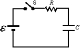 The values of the emf , resistance R, and the capacitance C for each of the circuits are
  Rank the circuits according to the time after switch S is closed for the capacitors to reach half their final charges, least to greatest.
(Multiple Choice)
4.8/5  (32)
(32)
Nine identical wires, each of diameter d and length L, are connected in series.The combination has the same resistance as a single similar wire of length L but whose diameter is:
(Multiple Choice)
4.9/5 (47)
Resistor 1 has twice the resistance of resistor 2.The two are connected in series and a potential difference is maintained across the combination.The rate of thermal energy dissipation in 1 is:
(Multiple Choice)
4.8/5 (38)
Resistor 1 has twice the resistance of resistor 2.The two are connected in parallel and a potential difference is maintained across the combination.The rate of thermal energy dissipation in 1 is:
(Multiple Choice)
4.8/5 (32)
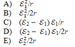
The positive terminals of two batteries with emf's of ε1 and ε2, respectively, are connected together.Here ε1 > ε2. The circuit is completed by connecting the negative terminals.If each battery has an internal resistance of r, the rate in watts at which electrical energy is converted to chemical energy in the smaller battery is:
(Multiple Choice)
4.7/5 (35)
A battery of emf 24 V is connected to a 6- resistor.As a result, current of 3 A exists in the resistor.The terminal potential difference of the battery is:
(Multiple Choice)
4.9/5 (44)
Two identical batteries, each with an emf of 18 V and an internal resistance of 1 , are wired in parallel by connecting their positive terminals together and connecting their negative terminals together.The combination is then wired across a 4- resistor.The current in the 4- resistor is:
(Multiple Choice)
4.8/5 (33)
"The sum of the emf's and potential differences around a closed loop equals zero" is a consequence of:
(Multiple Choice)
4.8/5 (47)
Two identical batteries, each with an emf of 18 V and an internal resistance of 1 , are wired in parallel by connecting their positive terminals together and connecting their negative terminals together.The combination is then wired across a 4- resistor.The current in each battery is:
(Multiple Choice)
4.9/5 (32)
In the figure, voltmeter V1 reads 600 V, voltmeter V2 reads 580 V, and ammeter A reads 100 A.The power wasted in the transmission line connecting the power house to the consumer is: 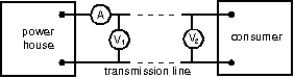
(Multiple Choice)
4.8/5 (34)
Each of the resistors in the diagram is 12 .The resistance of the entire circuit is: 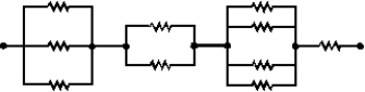
(Multiple Choice)
4.8/5 (33)
In the diagrams, all light bulbs are identical and all emf devices are identical.In which circuit (I, II, III, IV, V)will the bulbs be dimmest? 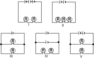
(Multiple Choice)
4.7/5 (30)
The circuit shown was wired for the purpose of measuring the resistance of the lamp L.Inspection shows that: 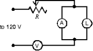
(Multiple Choice)
4.9/5 (35)
A 3- and a 1.5- resistor are wired in parallel and the combination is wired in series to a 4- resistor and a 10-V emf device.The current in the 3- resistor is:
(Multiple Choice)
4.8/5 (34)
Four 20- resistors are connected in series and the combination is connected to a 20-V emf device.The potential difference across any one of the resistors is:
(Multiple Choice)
4.9/5 (37)
In the capacitor discharge formula q = q0e-t/RC the symbol t represents:
(Multiple Choice)
4.9/5 (36)
A charged capacitor is being discharged through a resistor.At the end of one time constant the charge has been reduced by (1 - 1/e)= 63% of its initial value.At the end of two time constants the charge has been reduced by what percent of its initial value?
(Multiple Choice)
4.8/5 (32)
An ideal battery has an emf of 12 V.If it is connected to a circuit and creates a current of 4.0 A, what is the power?
(Multiple Choice)
4.8/5 (36)
Filters
- Essay(0)
- Multiple Choice(0)
- Short Answer(0)
- True False(0)
- Matching(0)