Exam 26: Dc Circuits
Exam 1: Introduction, Measurement, Estimating71 Questions
Exam 2: Describing Motion: Kinematics in One Dimension119 Questions
Exam 3: Kinematics in Two or Three Dimensions; Vectors100 Questions
Exam 4: Dynamics: Newtons Laws of Motion86 Questions
Exam 5: Using Newtons Laws: Friction, Circular Motion, Drag Forces68 Questions
Exam 6: Gravitation and Newtons6 Synthesis64 Questions
Exam 7: Work and Energy69 Questions
Exam 8: Conservation of Energy95 Questions
Exam 9: Linear Momentum85 Questions
Exam 10: Rotational Motion99 Questions
Exam 11: Angular Momentum; General Rotation45 Questions
Exam 12: Static Equilibrium; Elasticity and Fracture61 Questions
Exam 13: Fluids112 Questions
Exam 14: Oscillations102 Questions
Exam 15: Wave Motion74 Questions
Exam 16: Sound75 Questions
Exam 17: Temperature, Thermal Expansion, and the Ideal Gas Law83 Questions
Exam 18: Kinetic Theory of Gases37 Questions
Exam 19: Heat and the First Law of Thermodynamics96 Questions
Exam 20: Second Law of Thermodynamics77 Questions
Exam 21: Electric Charge and Electric Field97 Questions
Exam 22: Gausss Law44 Questions
Exam 23: Electric Potential70 Questions
Exam 24: Capacitance, Dielectrics, Electric Energy Storage73 Questions
Exam 25: Electric Currents and Resistance71 Questions
Exam 26: Dc Circuits110 Questions
Exam 27: Magnetism102 Questions
Exam 28: Sources of Magnetic Field63 Questions
Exam 29: Electromagnetic Induction and Faradays Law116 Questions
Exam 30: Inductance, Electromagnetic Oscillations, and Ac Circuits108 Questions
Exam 31: Maxwells Equations and Electromagnetic Waves76 Questions
Exam 32: Light: Reflection and Refraction118 Questions
Exam 33: Lenses and Optical Instruments134 Questions
Exam 34: The Wave Nature of Light; Interference77 Questions
Exam 35: Diffraction and Polarization68 Questions
Exam 36: Special Theory of Relativity69 Questions
Exam 37: Early Quantum Theory and Models of the Atom95 Questions
Exam 38: Quantum Mechanics42 Questions
Exam 39: Quantum Mechanics of Atoms62 Questions
Exam 40: Molecules and Solids56 Questions
Exam 41: Nuclear Physics and Radioactivity82 Questions
Exam 42: Nuclear Energy: Efects and Uses of Radiation69 Questions
Exam 43: Elementary Particle66 Questions
Exam 44: Astrophysics and Cosmology36 Questions
Select questions type
A small galvanometer coil of resistance R = 20 Ω and full-scale deflection at 1 mA is connected in series with a 4980 Ω resistance to build an analog voltmeter. What is the maximum voltage that this voltmeter can read?
Free
(Multiple Choice)
4.8/5  (34)
(34)
Correct Answer: Verified
D
A 4.0-μF capacitor is charged to 6.0-V. It is then connected in series with a 3.0-MΩ resistor and connected to a 12-V battery. How long after being connected to the battery will the voltage across the capacitor be 9.0 V?
Free
(Multiple Choice)
4.8/5 (42)
Correct Answer:Verified
C
FIGURE 26-8 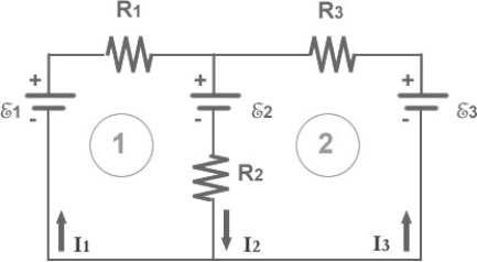 -For the circuit shown in Fig. 26-8, which equation is correct for loop2 (going clockwise)?
Free
(Multiple Choice)
4.8/5 (31)
Correct Answer:Verified
B
An analog ammeter able to have a 0.5 A maximum reading is to be built using a small coil of resistance R = 20 Ω, and full scale deflection at 1 mA. What resistance should be added to this coil and how should it be connected to the coil?
(Multiple Choice)
4.8/5 (28)
Four equal resistors connected across a DC voltage source in either series or parallel will have equal voltage drops across each resistor.
(True/False)
4.8/5 (39)
FIGURE 26-1 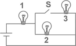 -Fig. 26-1 shows three identical lightbulbs connected to a battery. What happens to the brightness of lightbulb 1 when the switch S is closed?
(Multiple Choice)
4.8/5 (39)
Four unequal resistors are connected in a series circuit. Which one of the following statements is correct about this circuit?
(Multiple Choice)
4.8/5 (34)
A 6-Ω resistor, an 8-Ω resistor, and a 24-Ω resistor are connected together. What is the minimum resistance that can be produced using all three resistors?
(Multiple Choice)
4.9/5 (39)
FIGURE 26-16 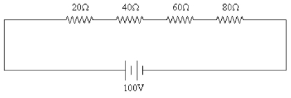 -A 100 V DC signal is applied to four resistors as shown in Fig. 26-16. The values of the resistors are 20 Ω, 40 Ω, 60 Ω, and 80 Ω. What is the voltage across the 40 Ω resistor?
(Multiple Choice)
4.8/5 (39)
In order to construct a voltmeter from a galvanometer, one normally would
(Multiple Choice)
4.7/5 (38)
As more resistors are added in series to a constant voltage source, the power supplied by the source
(Multiple Choice)
4.7/5 (31)
The potential difference between the terminals of a battery, when current flows to an external circuit, is referred to as the
(Multiple Choice)
4.8/5 (29)
An ideal voltmeter is one that does not change the behavior of a circuit when it is properly used to measure potential difference. The internal resistance of such a meter is
(Multiple Choice)
4.9/5 (35)
The electromotive force of a battery is the maximum potential difference between the terminals of the battery.
(True/False)
4.9/5 (30)
A 2.0-μF capacitor is charged to 12 V and then discharged through a 4.0 × 10⁶ Ω resistor. How long will it take for the voltage across the capacitor to drop to 3.0 V?
(Multiple Choice)
4.8/5 (40)
You obtain a 100-W light bulb and a 50-W light bulb. Instead of connecting them in the normal way, you devise a circuit that places them in series across normal household voltage. Which statement is correct?
(Multiple Choice)
4.8/5 (36)
FIGURE 26-29 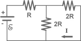 -In Fig. 26-29, I = 0.5 A and R = 12 Ω. What is the value of the emf E?
(Multiple Choice)
4.8/5 (21)
An RC circuit is connected across a DC voltage source through an open switch. As soon as the switch is closed, the capacitor charges linearly as a function of time.
(True/False)
4.9/5 (33)
FIGURE 26-24 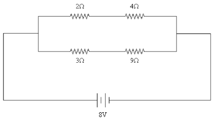 -Four resistors of values 2 Ω, 4 Ω, 3 Ω, and 9 Ω are connected across an 8-V DC source as shown in Fig. 26-24. What is the current through the 9-Ω resistor?
(Multiple Choice)
4.8/5 (33)
Filters
- Essay(0)
- Multiple Choice(0)
- Short Answer(0)
- True False(0)
- Matching(0)