Exam 4: Documenting Information Systems
Exam 1: Introduction to Accounting Information Systems122 Questions
Exam 2: Enterprise Systems141 Questions
Exam 3: Electronic Business E-Business Systems122 Questions
Exam 4: Documenting Information Systems129 Questions
Exam 5: Database Management Systems175 Questions
Exam 6: Relational Databases and SQL103 Questions
Exam 7: Controlling Information Systems: Introduction to Enterprise Risk Management and Internal Control161 Questions
Exam 8: Controlling Information Systems: Introduction to Pervasive Controls159 Questions
Exam 9: Controlling Information Systems: Business Process and Application Controls135 Questions
Exam 10: The Order Entrysales Oes Process134 Questions
Exam 11: The Billingaccounts Receivablecash Receipts Barcr Process134 Questions
Exam 12: The Purchasing Process141 Questions
Exam 13: The Accounts Payablecash Disbursements Apcd Process118 Questions
Exam 14: The Human Resources Process HR Management and Payroll Processes121 Questions
Exam 15: Integrated Production Processes IPP118 Questions
Exam 16: The General Ledger and Business Reporting GLBR Process107 Questions
Exam 17: Acquiring and Implementing Accounting Information Systems206 Questions
Select questions type
The successive subdividing, or "exploding," of physical data flow diagrams (DFDs) is called top-down partitioning.
(True/False)
4.9/5  (38)
(38)
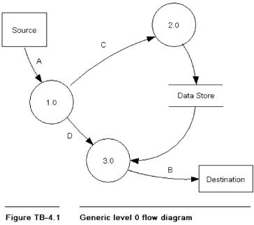
1. Figure TB-4.1 is a "generic" level 0 data flow diagram (DFD), taken from Figure 4.5 in the text.
Required:
Using good data flow diagram construction techniques draw a diagram to explode bubble 3.0 to its next lower level. Diagram 3.0 should contain three processes, appropriately numbered, and should contain the following data flows in addition to those in the level 0 diagram (see NOTE):
a. Flow H runs from the first process to the second.
b. Flow I runs from the first process to the third.
c. Flows J and K run from the second process to the third.
NOTE: Assume that the flows shown in the level 0 diagram affect diagram 3.0 as follows:
1. Flow D runs to the first process in diagram 3.0.
2. Flow B runs from the third process in diagram 3.0.
3. The data flow running from the data store runs to the second process in diagram 3.0.
(Essay)
4.7/5 (37)
In which of the following data flow diagrams does the bubble symbol represent a process and not the entire system?
(Multiple Choice)
4.8/5 (35)
Which of the following is the least detailed of the data flow diagrams?
(Multiple Choice)
4.8/5 (41)
In a data flow diagram (DFD), a(n) ______________________________ symbol depicts an entity or a process within which incoming data flows are transformed into outgoing data flows.
(Short Answer)
4.9/5 (36)
The following is a jumbled list of the activities suggested in this text for drafting data flow diagrams (DFDs) for an existing system:
I. Prepare a table of entities and activities.
II. Prepare an annotated table of entities and activities.
III. Draw a physical data flow diagram.
IV. Draw a logical data flow diagram.
V. Draw a context diagram.
The best sequence for undertaking these activities is:
(Multiple Choice)
4.8/5 (41)
Figure TB-4.5 shows a level 0 logical data flow diagram for a billing system. Also shown for reference is the context diagram for the system. The logical data flow diagram intentionally violates several of the guidelines and other techniques presented in the text for drawing data flow diagrams.
Required:
Identify as many of the errors in the logical data flow diagram construction as you can. In the logical data flow diagram, place consecutive numbers (each in a circle) next to the points at which the errors exist. On your solution sheet, list the numbers and write a one- to two-sentence description of each error and what the corrected diagram should depict. If an error occurs in more than one place, mark each occurrence of the error. Error 1 is provided as an example of how to construct the solution. Do not identify nor correct any errors that may exist on the context diagram.
1 \ The flow from bubble 2.1 to the Accounts receivable department is not labeled. The flow on the context diagram indicates that copy 3 of the sales invoice is sent to the accounts receivable department. Correction: Add a label to the flow from bubble 2.1 to the Accounts receivable department. But, because data flows on a logical data flow diagram (DFD) should describe the nature of the data not how the data are transmitted, we should label this flow "Record sales invoice" 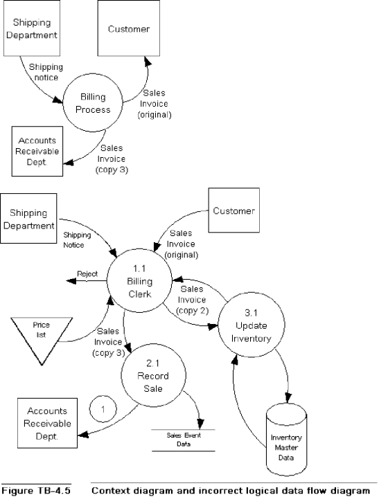
(Essay)
4.9/5 (37)
Data flow diagrams (DFDs) present a comprehensive picture of the management, operations, information systems and process controls embodied in business processes.
(True/False)
4.9/5 (32)
On a systems flowchart, computer processing is represented by a:
(Multiple Choice)
4.9/5 (40)
Which of the following systems flowcharting symbol descriptions is incorrect? a. b.
b. C.
C. d.
d.
(Multiple Choice)
4.8/5 (29)
A(n) ______________________________ gives a complete picture of a system by combining physical and logical aspects of the system.
(Short Answer)
4.8/5 (36)
Which of the following systems flowcharting symbols descriptions is incorrect?
a. b.
b. c.
c. d.
d.
(Multiple Choice)
4.8/5 (45)
The successive subdivision, or exploding, of logical data flow diagrams (DFDs) is called bottom up partitioning.
(True/False)
4.9/5 (41)
Which of the following systems flowcharting guidelines is correct?
(Multiple Choice)
4.9/5 (33)
Which data flow diagram (DFD) symbol is usually portrayed with an arrow?
(Multiple Choice)
4.8/5 (35)
A physical data flow diagram (DFD) uses bubbles to specify where, how, and by whom a system's processes are accomplished.
(True/False)
4.8/5 (41)
Data flow diagrams (DFDs) portray a business process' activities, stores of data, and flows of data among those elements.
(True/False)
4.8/5 (33)
______________________________ activities include retrieving data from storage, transforming data, or filing data.
(Short Answer)
4.8/5 (37)
Filters
- Essay(0)
- Multiple Choice(0)
- Short Answer(0)
- True False(0)
- Matching(0)