Exam 16: Regulators, Filters, and Op-Amps
Exam 1: Quantities and Units31 Questions
Exam 2: Voltage, Current, and Resistance69 Questions
Exam 3: Ohms Law, Energy, and Power64 Questions
Exam 4: Series Circuits64 Questions
Exam 5: Parallel Circuits62 Questions
Exam 6: Series-Parallel Circuits71 Questions
Exam 7: Magnetism and Electromagnetism66 Questions
Exam 8: Introduction to Alternating Current and Voltage66 Questions
Exam 9: Capacitors66 Questions
Exam 10: Rc Circuits65 Questions
Exam 11: Inductors62 Questions
Exam 12: Rl Circuits64 Questions
Exam 13: Rlc Circuits and Resonance68 Questions
Exam 14: Time Response of Reactive Circuits65 Questions
Exam 15: Transformers65 Questions
Exam 16: Regulators, Filters, and Op-Amps307 Questions
Exam 17: Understanding Transducers, Sensors, and Conversion in Industrial Processes80 Questions
Select questions type
 -If 22 V in the pass-band is input to the circuit in Figure 19-4,W hat is the output voltage at fCO?
(Multiple Choice)
4.7/5  (37)
(37)
In a P-N diode, the region near the P-N junction is called:
(Multiple Choice)
4.8/5 (40)
Butter worth filters are characterized by a linear response in the pass band.
(True/False)
4.9/5 (36)
 Figure
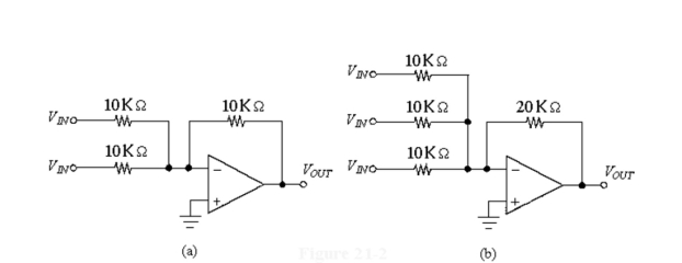
-If the inputs are 8.4 V and 1.2 V in Figure 19-2(a), the output voltage equals ________.
Figure
-If the inputs are 8.4 V and 1.2 V in Figure 19-2(a), the output voltage equals ________.
(Multiple Choice)
4.9/5 (41)
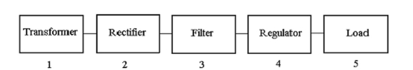 -Which block in Figure 16-2Will change the amplitude of the ac voltage?
(Multiple Choice)
4.7/5 (34)
The overall voltage gain of a multistage amplifier is the product of the individual stage gains.
(True/False)
4.8/5 (34)
Which one of these amplifiers does NOT have the output in phaseW ith the input?
(Multiple Choice)
4.7/5 (31)
Using op-amps in a triangularW ave oscillator results in a:
(Multiple Choice)
4.7/5 (42)
 Figure
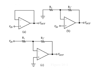
-If and in Figure 18-1(b), the voltage gain equals________
Figure
-If and in Figure 18-1(b), the voltage gain equals________
(Multiple Choice)
4.9/5 (45)
Figure
-Which of the amplifiers in Figure 18-1W ould be used as a buffer amplifier?
(Multiple Choice)
4.8/5 (41)
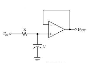 -If VIN equals 22 V in Figure 19-3, VOUT at the fCO equals______
(Multiple Choice)
4.9/5 (30)
If a full-wave rectifier outputs 36 VP , the average output is _______
(Multiple Choice)
4.8/5 (37)
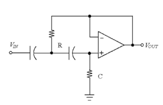
If an inverting amplifier has a capacitor in the feedback loop, the circuit is known as the ________. When a square wave input is applied, the output is a ________wave.
(Multiple Choice)
4.9/5 (40)
An op-ampʹs input offset voltage, VOS, is the differential input voltage required to make the differential output voltage zero.
(True/False)
4.7/5 (24)
 -Which voltage would indicate that the amplifier in Figure 17-4 is operating in saturation?
(Multiple Choice)
4.8/5 (33)
Figure
-What change causes the circuit in Figure 19-2(b) to output the average of the three input voltages?
(Multiple Choice)
4.8/5 (32)
Filters
- Essay(0)
- Multiple Choice(0)
- Short Answer(0)
- True False(0)
- Matching(0)