Exam 28: Fundamentals of Circuits
Exam 1: Concepts of Motion52 Questions
Exam 2: Kinematics in One Dimension59 Questions
Exam 3: Vectors and Coordinate Systems33 Questions
Exam 4: Kinematics in Two Dimensions49 Questions
Exam 5: Force and Motion30 Questions
Exam 6: Dynamics I: Motion Along a Line46 Questions
Exam 7: Newtons Third Law43 Questions
Exam 8: Dynamics II: Motion in a Plane20 Questions
Exam 9: Work and Kinetic Energy66 Questions
Exam 10: Interactions and Potential Energy55 Questions
Exam 11: Impulse and Momentum43 Questions
Exam 12: Rotation of a Rigid Body116 Questions
Exam 13: Newtons Theory of Gravity50 Questions
Exam 14: Fluids and Elasticity72 Questions
Exam 15: Oscillations49 Questions
Exam 16: Traveling Waves51 Questions
Exam 17: Superposition51 Questions
Exam 18: A Macroscopic Description of Matter46 Questions
Exam 19: Work, heat, and the First Law of Thermodynamics96 Questions
Exam 20: The Micromacro Connection41 Questions
Exam 21: Heat Engines and Refrigerators44 Questions
Exam 22: Electric Charges and Forces26 Questions
Exam 23: The Electric Field32 Questions
Exam 24: Gausss Law41 Questions
Exam 25: The Electric Potential40 Questions
Exam 26: Potential and Field57 Questions
Exam 27: Current and Resistance32 Questions
Exam 28: Fundamentals of Circuits68 Questions
Exam 29: The Magnetic Field83 Questions
Exam 30: Electromagnetic Induction66 Questions
Exam 31: Electromagnetic Fields and Waves52 Questions
Exam 32: Ac Circuits44 Questions
Exam 33: Wave Optics51 Questions
Exam 34: Ray Optics60 Questions
Exam 35: Optical Instruments52 Questions
Exam 36: Relativity49 Questions
Exam 37: The Foundations of Modern Physics7 Questions
Exam 38: Quantization45 Questions
Exam 39: Wave Functions and Uncertainty18 Questions
Exam 40: One-Dimensional Quantum Mechanics32 Questions
Exam 41: Atomic Physics38 Questions
Exam 42: Nuclear Physics64 Questions
Select questions type
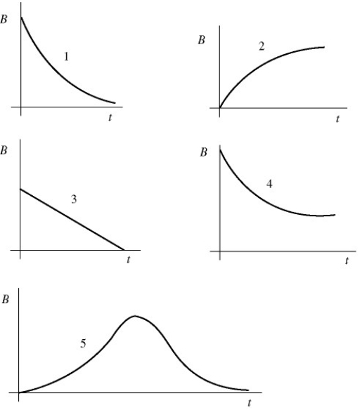
A light bulb is connected in the circuit shown in the figure with the switch S open and the capacitor uncharged.The battery has no appreciable internal resistance.Which one of the following graphs best describes the brightness B of the bulb as a function of time t after closing the switch? 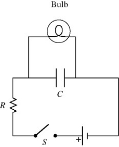
Free
(Multiple Choice)
4.7/5  (38)
(38)
Correct Answer: Verified
B
A galvanometer with a resistance of 40.0 Ω deflects full scale at a current of 2.0 mA.What resistance should be used with this galvanometer in order to construct a voltmeter that can read a maximum of 50 V?
Free
(Multiple Choice)
4.8/5 (35)
Correct Answer:Verified
A
In the circuit shown in the figure,two 360.0-Ω resistors are connected in series with an ideal source of emf.A voltmeter with internal resistance of 6350 Ω is connected across one of the resistors and reads 3.23 V.Find the emf of the source. 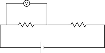
Free
(Short Answer)
4.8/5 (29)
Correct Answer:Verified
6.64 V
For the circuit shown in the figure,what is the current through resistor R3? 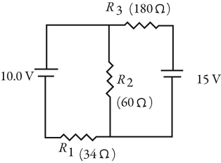
(Multiple Choice)
4.9/5 (40)
For the circuit shown in the figure,determine the current in
(a)the 7.0-Ω resistor.
(b)the 8.0-Ω resistor.
(c)the 4.0-Ω resistor. 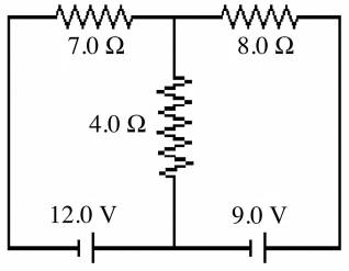
(Short Answer)
4.9/5 (34)
A 6.0-μF capacitor is connected in series with a 5.0 MΩ resistor,and this combination is connected across an ideal 15-V DC battery.What is the current in the circuit when the capacitor has reached 20% of its maximum charge?
(Multiple Choice)
4.8/5 (40)
For the circuit shown in the figure,the current in the 8-Ω resistor is 0.50 A,and all quantities are accurate to 2 significant figures.What is the current in the 2-Ω resistor? 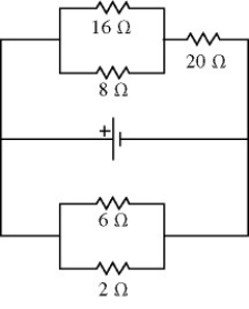
(Multiple Choice)
4.9/5 (38)
For the circuit shown in the figure,all quantities are accurate to 2 significant figures.What is the value of the current I1? 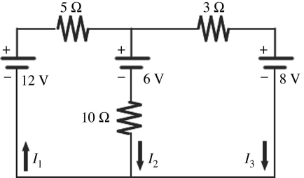
(Multiple Choice)
4.8/5 (40)
A resistor is made out of a long wire having a length L.Each end of the wire is attached to a terminal of a battery providing a constant voltage V0.A current I flows through the wire.If the wire were cut in half,making two wires of length L/2,and both wires were attached to the battery (the end of both wires attached to one terminal,and the other ends attached to the other terminal),what would be the total current flowing through the two wires?
(Multiple Choice)
4.8/5 (45)
A multiloop circuit is shown in the figure.Some circuit quantities are not labeled.It is not necessary to solve the entire circuit.The current I1 is closest to 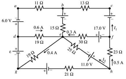
(Multiple Choice)
4.7/5 (26)
In the figure a current of 6.0 A is drawn from the battery.What is the terminal voltage Vab of the battery? 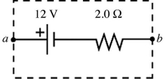
(Multiple Choice)
4.9/5 (35)
Two unknown resistors are connected together.When they are connected in series their equivalent resistance is 15 Ω.When they are connected in parallel,their equivalent resistance is 3.3 Ω.What are the resistances of these resistors?
(Short Answer)
4.9/5 (42)
For the circuit shown in the figure,I = 0.50 A and R = 12 Ω.What is the value of the emf ε? 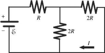
(Multiple Choice)
4.8/5 (36)
An uncharged 1.0-μF capacitor is connected in series with a  resistor,an ideal
  battery,and an open switch.What is the voltage across the capacitor
  after closing the switch?
(Multiple Choice)
4.7/5 (27)
For the circuit shown in the figure,all quantities are accurate to 3 significant figures.What is the power dissipated in the 2-Ω resistor? 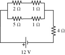
(Multiple Choice)
4.8/5 (28)
A 4.0-μF capacitor that is initially uncharged is connected in series with a 4.0-kΩ resistor and an ideal 17.0-V battery.How much energy is stored in the capacitor 17 ms after the battery has been connected?
(Multiple Choice)
4.9/5 (34)
Thirteen resistors are connected across points A and B as shown in the figure.If all the resistors are accurate to 2 significant figures,what is the equivalent resistance between points A and B? 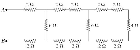
(Multiple Choice)
4.8/5 (40)
A galvanometer G has an internal resistance rg.A VOLTMETER is constructed by incorporating the galvanometer and an additional resistance Rs.Which one of the figures below is the most appropriate circuit diagram for the voltmeter? 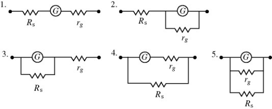
(Multiple Choice)
4.9/5 (40)
For the circuit shown in the figure,the switch S is initially open and the capacitor is uncharged.The switch is then closed at time t = 0.How many seconds after closing the switch will the energy stored in the capacitor be equal to 50.2 mJ? 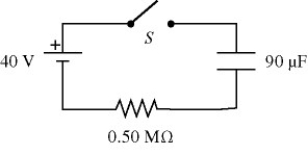
(Multiple Choice)
4.9/5 (36)
In the circuit shown in the figure,an ideal ohmmeter is connected across ab with the switch S open.All the connecting leads have negligible resistance.The reading of the ohmmeter will be closest to 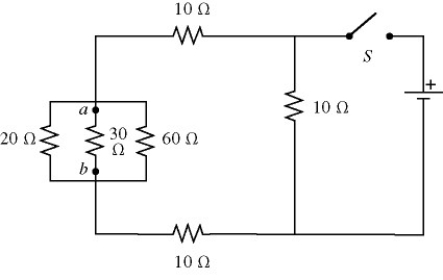
(Multiple Choice)
4.8/5 (41)
Filters
- Essay(0)
- Multiple Choice(0)
- Short Answer(0)
- True False(0)
- Matching(0)