Exam 7: BJT Biasing
Exam 1: Introduction38 Questions
Exam 2: Semoconductors50 Questions
Exam 3: Diode Theory Key50 Questions
Exam 4: Diode Circuits48 Questions
Exam 5: Special-Purpose Diodes Key50 Questions
Exam 6: BJT Fumdamentals50 Questions
Exam 7: BJT Biasing50 Questions
Exam 7: Basic BJT Amplifiers52 Questions
Exam 9: Multistage,CC,and CB Amplifiers50 Questions
Exam 10: Power Amplifiers48 Questions
Exam 11: JFETS50 Questions
Exam 12: Mosfets46 Questions
Exam 13: Thyristors50 Questions
Exam 14: Frequency Effects50 Questions
Exam 15: Differential Amplifiers50 Questions
Exam 16: Operational Amplifiers50 Questions
Exam 17: Negative Feedback49 Questions
Exam 18: Linear OP AMP Circuits50 Questions
Exam 19: Active Filters Key50 Questions
Exam 20: Nonlinear Op-Amp Circuit Applications Key50 Questions
Exam 21: Oscillators Key50 Questions
Exam 22: Regulated Power Supplies Key49 Questions
Select questions type
In order to determine the emitter current for the circuit shown in Figure 7-21,you must 
Free
(Multiple Choice)
4.9/5  (31)
(31)
Correct Answer: Verified
A
While troubleshooting the circuit shown in Figure 7-26,the base voltage measures 1.8 V and the collector voltage measures 10 V,what should the technician do? 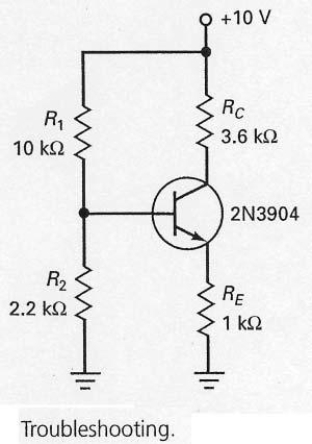
Free
(Multiple Choice)
4.8/5 (50)
Correct Answer:Verified
A
To prevent meter loading,a voltmeter used to make transistor circuit voltage measurements should have an input impedance of ________.
Free
(Multiple Choice)
4.8/5 (28)
Correct Answer:Verified
D
Whenever you have a circuit with npn transistors,you can often use the same circuit with pnp transistors and
(Multiple Choice)
4.7/5 (36)
Collector-feedback bias is still sensitive to changes in current gain,but it is used because of its
(Multiple Choice)
4.8/5 (30)
Once the base voltage has been calculated for the circuit shown in Figure 7-29 (b),emitter voltage can be calculated by 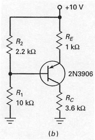
(Multiple Choice)
4.9/5 (35)
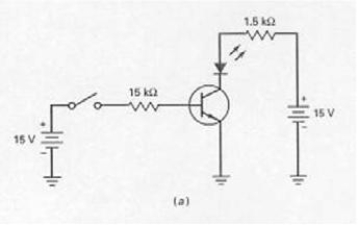
With the switch in the position as shown in Figure 7-4 (a),the LED is on.
(True/False)
4.9/5 (43)
Since voltage-divider bias is derived from emitter bias,the Q point is virtually immune to changes in current gain.

(True/False)
5.0/5 (38)
In Figure 7-21,what effect do the capacitors have on the bias voltage in each stage? 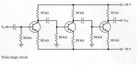
(Multiple Choice)
4.8/5 (38)
The biasing configuration shown in Figure 7-18 is derived from emitter bias and is referred to as 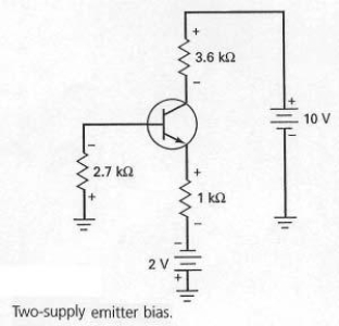
(Multiple Choice)
4.9/5 (34)
If RE is adjusted to its maximum value in Figure 7-16,the Q point moves toward saturation.
(True/False)
4.8/5 (34)
What should a troubleshooter do if the base,collector,and emitter voltages in a transistor circuit all measure 0 V?
(Multiple Choice)
4.7/5 (35)
Using a firm voltage divider means that the collector current will be approximately
(Multiple Choice)
4.8/5 (39)
A well-designed voltage-divider bias circuit is one in which the voltage divider appears stiff to the input resistance of the base.
(True/False)
4.8/5 (42)
Filters
- Essay(0)
- Multiple Choice(0)
- Short Answer(0)
- True False(0)
- Matching(0)