Exam 27: Circuits
Exam 1: Measurement31 Questions
Exam 2: Motion Along a Straight Line79 Questions
Exam 3: Vector39 Questions
Exam 4: Motion in Two and Three Dimensions47 Questions
Exam 5: Force and Motion I68 Questions
Exam 6: Force and Motion II71 Questions
Exam 7: Kinetic Energy and Work67 Questions
Exam 8: Potential Energy and Conservation of Energy61 Questions
Exam 9: Center of Mass and Linear Momentum81 Questions
Exam 10: Rotation82 Questions
Exam 11: Rolling, Torque, and Angular Momentum54 Questions
Exam 12: Equilibrium and Elasticity53 Questions
Exam 13: Gravitation55 Questions
Exam 14: Fluids85 Questions
Exam 15: Oscillations62 Questions
Exam 16: Waves I71 Questions
Exam 17: Waves II61 Questions
Exam 18: Temperature, Heat, and the First Law of Thermodynamics82 Questions
Exam 19: The Kinetic Theory of Gases95 Questions
Exam 20: Entropy and the Second Law of Thermodynamics56 Questions
Exam 21: Electric Charge45 Questions
Exam 22: Electric Fields49 Questions
Exam 23: Gauss Law34 Questions
Exam 24: Electric Potential44 Questions
Exam 25: Capacitance55 Questions
Exam 26: Current and Resistance49 Questions
Exam 27: Circuits70 Questions
Exam 28: Magnetic Fields48 Questions
Exam 29: Magnetic Fields Due to Currents47 Questions
Exam 30: Induction and Inductance85 Questions
Exam 31: Electromagnetic Oscillations and Alternating Current84 Questions
Exam 32: Maxwells Equations; Magnetism of Matter81 Questions
Exam 33: Electromagnetic Waves79 Questions
Exam 34: Images72 Questions
Exam 35: Interference40 Questions
Exam 36: Diffraction74 Questions
Exam 37: Relativity65 Questions
Exam 38: Photons and Matter Waves53 Questions
Exam 39: More About Matter Waves41 Questions
Exam 40: All About Atoms76 Questions
Exam 41: Conduction of Electricity in Solids48 Questions
Exam 42: Nuclear Physics67 Questions
Exam 43: Energy From the Nucleus44 Questions
Exam 44: Quarks, Leptons, and the Big Bang52 Questions
Select questions type
Resistances of 2.0 , 4.0 , and 6.0 and a 24-V emf device are all in series. The potential difference across the 2.0- resistor is:
(Multiple Choice)
4.8/5  (44)
(44)
Four wires meet at a junction. The first carries 4A into the junction, the second carries 5A out of the junction, and the third carries 2A out of the junction. The fourth carries:
(Multiple Choice)
4.9/5 (35)
A certain voltmeter has an internal resistance of 10,000 and a range from 0 to 100 V. To give it a range from 0 to 1000 V, one should connect:
(Multiple Choice)
4.8/5 (41)
In the diagrams, all light bulbs are identical and all emf devices are identical. In which circuit (I, II, III, IV, V) will the bulbs be dimmest? 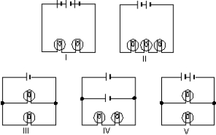
(Multiple Choice)
4.9/5 (42)
A series circuit consists of a battery with internal resistance r and an external resistor R. If these two resistances are equal (r = R) then the energy dissipated per unit time by the internal resistance r is:
(Multiple Choice)
4.8/5 (34)
A battery with an emf of 12 V and an internal resistance of 1 is used to charge a battery with an emf of 10 V and an internal resistance of 1 . The current in the circuit is:
(Multiple Choice)
4.9/5 (27)
A battery has an emf of 9V and an internal resistance of 2 . If the potential difference across its terminals is greater than 9V:
(Multiple Choice)
4.8/5 (37)
Four 20- resistors are connected in series and the combination is connected to a 20-V emf device. The potential difference across any one of the resistors is:
(Multiple Choice)
5.0/5 (37)
"The sum of the currents into a junction equals the sum of the currents out of the junction" is a consequence of:
(Multiple Choice)
5.0/5 (40)
Four circuits have the form shown in the diagram. The capacitor is initially uncharged and the switch S is open. 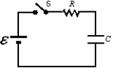 The values of the emf , resistance R, and the capacitance C for each of the circuits are
  Rank the circuits according to the time after switch S is closed for the capacitors to reach half their final charges, least to greatest.
(Multiple Choice)
4.9/5 (33)
The equivalent resistance between points 1 and 2 of the circuit shown is: 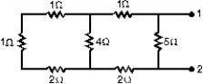
(Multiple Choice)
4.8/5 (37)
In the diagram, the current in the 3- resistor is 4 A. The potential difference between points 1 and 2 is: 
(Multiple Choice)
4.8/5 (43)
The terminal potential difference of a battery is less greater than its emf:
(Multiple Choice)
4.9/5 (40)
The resistance of resistor 1 is twice the resistance of resistor 2. The two are connected in series and a potential difference is maintained across the combination. Then:
(Multiple Choice)
4.8/5 (37)
In the figure, voltmeter V1 reads 600 V, voltmeter V2 reads 580 V, and ammeter A reads 100 A. The power wasted in the transmission line connecting the power house to the consumer is: 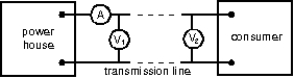
(Multiple Choice)
4.8/5 (35)
A resistor with resistance R1 and a resistor with resistance R2 are connected in parrallel to an ideal battery with emf ε. The rate of thermal energy generation in the resistor with resistance R1 is:
(Multiple Choice)
4.8/5 (46)
Each of the resistors in the diagram is 12 . The resistance of the entire circuit is: 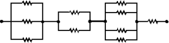
(Multiple Choice)
4.7/5 (35)
A battery is connected across a parallel combination of two identical resistors. If the potential difference across the terminals is V and the current in the battery is i, then:
(Multiple Choice)
4.9/5 (41)
A certain capacitor, in series with a 720- resistor, is being charged. At the end of 10 ms its charge is half the final value. The capacitance is about:
(Multiple Choice)
4.9/5 (38)
Filters
- Essay(0)
- Multiple Choice(0)
- Short Answer(0)
- True False(0)
- Matching(0)