Exam 23: Circuits
Exam 1: Representing Motion113 Questions
Exam 2: Motion in One Dimension172 Questions
Exam 3: Vectors and Motion in Two Dimensions180 Questions
Exam 4: Forces and Newtons Laws of Motion64 Questions
Exam 5: Applying Newtons Laws82 Questions
Exam 6: Gravity96 Questions
Exam 7: Rotational Motion95 Questions
Exam 8: Equilibrium Ad Elasticity72 Questions
Exam 9: Momentum103 Questions
Exam 10: Energy and Work219 Questions
Exam 11: Using Energy106 Questions
Exam 12: Thermal Properties of Matter220 Questions
Exam 13: Fluids112 Questions
Exam 14: Oscillations105 Questions
Exam 15: Traveling Waves and Sound94 Questions
Exam 16: Superposition and Standing Waves66 Questions
Exam 17: Wave Optics129 Questions
Exam 18: Ray Optics154 Questions
Exam 19: Optical Instruments137 Questions
Exam 20: Electric Fields and Forces86 Questions
Exam 21: Electric Potential140 Questions
Exam 22: Current and Resistance124 Questions
Exam 23: Circuits145 Questions
Exam 24: Magnetic Fields and Forces155 Questions
Exam 25: Em Induction and Em Waves184 Questions
Exam 26: Ac Electricity122 Questions
Exam 27: Relativity125 Questions
Exam 28: Quantum Physics85 Questions
Exam 29: Atoms and Molecules105 Questions
Exam 30: Nuclear Physics175 Questions
Select questions type
A number of resistors are connected across points A and B as shown in the figure. What is the equivalent resistance between points A and B? 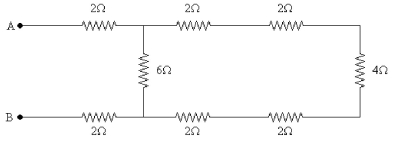
Free
(Multiple Choice)
4.8/5  (39)
(39)
Correct Answer: Verified
C
A group of 1.0-μF, 2.0-μF, and 3.0-μF capacitors is connected in parallel across a 24-V potential difference (a battery). How much energy is stored in this three-capacitor combination when the capacitors are fully charged?
Free
(Multiple Choice)
4.8/5 (41)
Correct Answer:Verified
A
Three capacitors are connected as shown in the figure. What is the equivalent capacitance between points A and B? 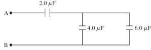
Free
(Multiple Choice)
5.0/5 (35)
Correct Answer:Verified
D
A portion of a circuit is shown in the figure, and the batteries are ideal. What is the potential difference VA - VB if I = 5.0 A? 
(Multiple Choice)
4.9/5 (35)
In the circuit shown in the figure, the resistor R has a variable resistance. As R is decreased, what happens to the currents? 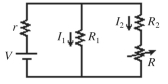
(Multiple Choice)
4.8/5 (41)
Three resistors with resistances of 2.0 Ω, 6.0 Ω, and 12 Ω are connected across an ideal dc voltage source V, as shown in the figure. If the total current in the circuit is I = 5.0 A, what is the current through the 12-Ω resistor? 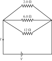
(Multiple Choice)
4.8/5 (37)
A multiloop circuit is shown in the figure, but some quantities are not labeled. Find the current I2 if the batteries are ideal. (It is not necessary to solve the entire circuit.) 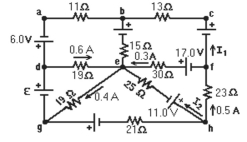
(Multiple Choice)
4.9/5 (34)
If 1.5 A flows through R2, what is the emf V of the ideal battery in the figure? 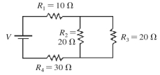
(Multiple Choice)
5.0/5 (44)
Determine the current in the 8.0-Ω resistor for the circuit shown in the figure. Assume that the batteries are ideal and that all numbers are accurate to two significant figures. 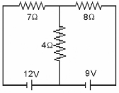
(Multiple Choice)
4.8/5 (39)
A circuit contains a 2.0-M? resistor in series with an uncharged capacitor. When this combination is connected across an ideal battery, the capacitor reaches 25% of its maximum charge in 1.5 s. What is its capacitance?
(Short Answer)
5.0/5 (30)
A certain 20-A circuit breaker trips when the current in it equals 20 A. What is the maximum number of 100-W light bulbs you can connect in parallel in an ideal 120-V dc circuit without tripping this circuit breaker?
(Multiple Choice)
4.8/5 (40)
For the circuit shown in the figure, the current in the 8.0-Ω resistor is 0.50A. What is the current in the 2.0-Ω resistor? All the numbers shown are accurate to two significant figures. 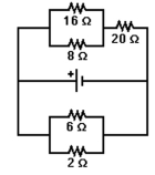
(Multiple Choice)
4.8/5 (30)
A system of four capacitors is connected across a 90-V voltage source as shown in the figure. What is the equivalent capacitance of this system? 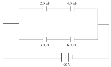
(Multiple Choice)
4.9/5 (30)
What resistance must be connected in parallel with a 633-? resistor to produce an equivalent resistance of 205 ??
(Short Answer)
4.8/5 (36)
What is the magnitude of the potential difference between points A and C for the circuit shown in the figure? The battery is ideal, and all the numbers are accurate to two significant figures. 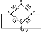
(Multiple Choice)
4.9/5 (37)
Four 16-?F capacitors are connected in combination. What is the equivalent capacitance of this combination if they are connected
(a)in series?
(b)in parallel?
(c)such that two of them are in parallel with each other and that combination is in series with the remaining two capacitors?
(Short Answer)
4.8/5 (41)
For the circuit shown in the figure, V = 60 V, C = 40 µF, R = 0.90 MΩ, and the battery is ideal. Initially the switch S is open and the capacitor is uncharged. The switch is then closed at time t = 0.00 s. At a given instant after closing the switch, the potential difference across the capacitor is twice the potential difference across the resistor. At that instant, what is the charge on the capacitor? 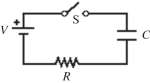
(Multiple Choice)
4.8/5 (38)
Three capacitors are arranged as shown in the figure, with a voltage source connected across the combination. C1 has a capacitance of has a capacitance of and has a capacitance of Find the potential drop across the entire arrangement if the potential drop across C2 is 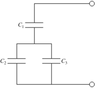
(Multiple Choice)
4.7/5 (25)
For the circuit shown in the figure, C = 12 µF and R = 8.5 MΩ. Initially the switch S is open with the capacitor charged to a voltage of 80 V. The switch is then closed at time t = 0.00 s. What is the charge on the capacitor, when the current in the circuit is 3.3 µA? 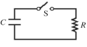
(Multiple Choice)
4.8/5 (37)
Four resistors having resistances of 20 Ω, 40 Ω, 60 Ω, and 80 Ω are connected in series across an ideal 50-V dc source. What is the current through each resistor?
(Multiple Choice)
4.8/5 (28)
Filters
- Essay(0)
- Multiple Choice(0)
- Short Answer(0)
- True False(0)
- Matching(0)