Exam 23: Circuits
Exam 1: Representing Motion113 Questions
Exam 2: Motion in One Dimension172 Questions
Exam 3: Vectors and Motion in Two Dimensions180 Questions
Exam 4: Forces and Newtons Laws of Motion64 Questions
Exam 5: Applying Newtons Laws82 Questions
Exam 6: Gravity96 Questions
Exam 7: Rotational Motion95 Questions
Exam 8: Equilibrium Ad Elasticity72 Questions
Exam 9: Momentum103 Questions
Exam 10: Energy and Work219 Questions
Exam 11: Using Energy106 Questions
Exam 12: Thermal Properties of Matter220 Questions
Exam 13: Fluids112 Questions
Exam 14: Oscillations105 Questions
Exam 15: Traveling Waves and Sound94 Questions
Exam 16: Superposition and Standing Waves66 Questions
Exam 17: Wave Optics129 Questions
Exam 18: Ray Optics154 Questions
Exam 19: Optical Instruments137 Questions
Exam 20: Electric Fields and Forces86 Questions
Exam 21: Electric Potential140 Questions
Exam 22: Current and Resistance124 Questions
Exam 23: Circuits145 Questions
Exam 24: Magnetic Fields and Forces155 Questions
Exam 25: Em Induction and Em Waves184 Questions
Exam 26: Ac Electricity122 Questions
Exam 27: Relativity125 Questions
Exam 28: Quantum Physics85 Questions
Exam 29: Atoms and Molecules105 Questions
Exam 30: Nuclear Physics175 Questions
Select questions type
A 2.0-μF capacitor that is initially uncharged is charged through a 50-kΩ resistor. How long does it take for the capacitor to reach 90% of its full charge?
(Multiple Choice)
4.9/5  (38)
(38)
A 1.0-?F capacitor is charged until it acquires a potential difference of across its plates, and then the emf source is removed. If the capacitor is then discharged through a resistance, what is the voltage drop across the capacitor after beginning the discharge?
(Multiple Choice)
4.9/5 (33)
In the circuit shown in the figure, all the capacitors are initially uncharged when the switch S is suddenly closed, and the battery is ideal. Find (a)the maximum reading of the ammeter and (b)the maximum charge on the 5.00-µF capacitor. 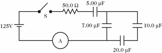
(Short Answer)
4.8/5 (33)
What is the equivalent resistance between points A and B of the network shown in the figure? 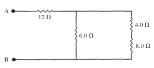
(Short Answer)
4.7/5 (34)
A 3.0-Ω resistor is connected in parallel with a 6.0-Ω resistor. This combination is then connected in series with a 4.0-Ω resistor. The resistors are connected across an ideal 12-volt battery. How much power is dissipated in the 3.0-Ω resistor?
(Multiple Choice)
4.8/5 (42)
A 8.0-μF uncharged capacitor is connected in series with a 6.0-kΩ resistor, an ideal 20-V dc source, and an open switch. If the switch is closed at time t = 0.0 s, what is the charge on the capacitor at t = 9.0 ms?
(Multiple Choice)
4.9/5 (35)
When unequal resistors are connected in series across an ideal battery,
(Multiple Choice)
4.9/5 (33)
A 4.0-Ω resistor is connected with a 12-Ω resistor and both of these are connected across an ideal dc power supply with voltage V as shown in the figure. If the total current in this circuit is I = 2.0 A, what is the current through the 4.0-Ω resistor? 
(Multiple Choice)
4.8/5 (31)
Three identical capacitors are connected in parallel to a potential source (battery). If a charge of Q flows into this combination, how much charge does each capacitor carry?
(Multiple Choice)
4.7/5 (41)
For the circuit shown in the figure, what is the power dissipated in the 2.0-Ω resistor? All the numbers shown are accurate to three significant figures. 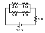
(Multiple Choice)
4.8/5 (45)
A combination of a 2.0-Ω resistor in series with 4.0-Ω resistor is connected in parallel with a 3.0-Ω resistor. What is the equivalent resistance of this system?
(Multiple Choice)
4.8/5 (40)
A 4.0-Ω resistor is connected to a 12-Ω resistor and this combination is connected to an ideal dc power supply with voltage V as shown in the figure. If the total current in this circuit is I = 2.0 A, what is the value of voltage V? 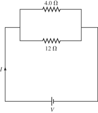
(Multiple Choice)
4.9/5 (32)
A fully charged 37-µF capacitor is discharged through a 1.0-kΩ resistor. If the voltage across the capacitor is reduced to 7.6 volts after just 20 ms, what was the original potential across the capacitor?
(Multiple Choice)
4.7/5 (38)
A system of four capacitors is connected across a 90-V voltage source as shown in the figure.
(a)What is the potential difference across the plates of the 6.0-µF capacitor?
(b)What is the charge on the 3.0-µF capacitor? 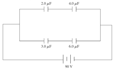
(Short Answer)
4.8/5 (40)
Three resistors with resistances of 2.0 Ω, 6.0 Ω, and 12 Ω are connected across an ideal dc voltage source V as shown in the figure. If the total current through the circuit is I = 2.0 A, what is the applied voltage V? 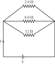
(Multiple Choice)
4.9/5 (40)
Determine the current in the 7.0-Ω resistor for the circuit shown in the figure. Assume that the batteries are ideal and that all numbers are accurate to two significant figures. 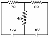
(Multiple Choice)
4.8/5 (34)
When unequal resistors are connected in parallel in a circuit,
(Multiple Choice)
5.0/5 (36)
If emf of the ideal battery is V = 100 V, what is the potential difference across R5 for the circuit shown in the figure? 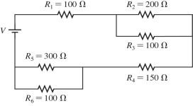
(Multiple Choice)
4.9/5 (37)
A resistor is made out of a wire having a length L. When the ends of the wire are attached across the terminals of an ideal battery having a constant voltage V0 across its terminals, a current I flows through the wire. If the wire were cut in half, making two wires of length L/2, and both wires were attached across the terminals of the battery (the right ends of both wires attached to one terminal, and the left ends attached to the other terminal), how much current would the battery put out?
(Multiple Choice)
4.8/5 (43)
A multiloop circuit is shown in the figure, but some quantities are not labeled. Find the current I1 if the batteries are ideal. (It is not necessary to solve the entire circuit.) 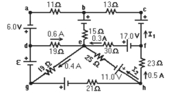
(Multiple Choice)
5.0/5 (34)
Filters
- Essay(0)
- Multiple Choice(0)
- Short Answer(0)
- True False(0)
- Matching(0)