Exam 23: Circuits
Exam 1: Representing Motion113 Questions
Exam 2: Motion in One Dimension172 Questions
Exam 3: Vectors and Motion in Two Dimensions180 Questions
Exam 4: Forces and Newtons Laws of Motion64 Questions
Exam 5: Applying Newtons Laws82 Questions
Exam 6: Gravity96 Questions
Exam 7: Rotational Motion95 Questions
Exam 8: Equilibrium Ad Elasticity72 Questions
Exam 9: Momentum103 Questions
Exam 10: Energy and Work219 Questions
Exam 11: Using Energy106 Questions
Exam 12: Thermal Properties of Matter220 Questions
Exam 13: Fluids112 Questions
Exam 14: Oscillations105 Questions
Exam 15: Traveling Waves and Sound94 Questions
Exam 16: Superposition and Standing Waves66 Questions
Exam 17: Wave Optics129 Questions
Exam 18: Ray Optics154 Questions
Exam 19: Optical Instruments137 Questions
Exam 20: Electric Fields and Forces86 Questions
Exam 21: Electric Potential140 Questions
Exam 22: Current and Resistance124 Questions
Exam 23: Circuits145 Questions
Exam 24: Magnetic Fields and Forces155 Questions
Exam 25: Em Induction and Em Waves184 Questions
Exam 26: Ac Electricity122 Questions
Exam 27: Relativity125 Questions
Exam 28: Quantum Physics85 Questions
Exam 29: Atoms and Molecules105 Questions
Exam 30: Nuclear Physics175 Questions
Select questions type
You obtain a 100-W light bulb and a 50-W light bulb. Instead of connecting them in the normal way, you devise a circuit that places them in series across normal household voltage. If each one is an incandescent bulb of fixed resistance, which statement about these bulbs is correct?
(Multiple Choice)
4.8/5  (37)
(37)
Three capacitors of equal capacitance are arranged as shown in the figure, with a voltage source across the combination. If the voltage drop across C1 is what is the voltage drop across 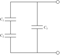
(Multiple Choice)
4.7/5 (35)
The following three appliances are connected in parallel across an ideal 120-V dc power source: 1200-W toaster, 650-W coffee pot, and 600-W microwave. If all were operated at the same time what total current would they draw from the source?
(Multiple Choice)
5.0/5 (42)
As more resistors are added in parallel across a constant voltage source, the power supplied by the source
(Multiple Choice)
5.0/5 (41)
A 5.0-μF, a 14-μF, and a 21-μF capacitor are connected in series. How much capacitance would a single capacitor need to have to replace the three capacitors?
(Multiple Choice)
4.8/5 (42)
An ideal 100-V dc battery is applied across a series combination of four resistors having resistances of 20 Ω, 40 Ω, 60 Ω, and 80 Ω. What is the potential difference across the 40-Ω resistor?
(Multiple Choice)
4.9/5 (41)
An ideal 10.0-V dc is connected across a resistor in series with an resistor. What is the potential drop across the resistor?
(Multiple Choice)
4.9/5 (40)
Determine the current in the 12-Ω resistor for the circuit shown in the figure assuming that the batteries are ideal. 
(Multiple Choice)
4.7/5 (32)
For the circuit shown in the figure, R1 = 18 ?, R2 = 44 ?, R3 = 33 ?, R4 = 14 ?, R5 = 12 ?, V1 = 18 V, V2 = 12 V, and the batteries are ideal. Determine I1 and I2. 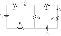
(Short Answer)
4.9/5 (30)
A capacitor C is connected in series with a resistor R across a battery and an open switch. If a second capacitor of capacitance 2C is connected in parallel with the first one, the time constant of the new RC circuit will be
(Multiple Choice)
4.7/5 (30)
If V = 40 V and the battery is ideal, what is the potential difference across R1 in the figure? 
(Multiple Choice)
4.7/5 (38)
A multiloop circuit is shown in the figure. Find the current I2 if the batteries are ideal. (It is not necessary to solve the entire circuit.) 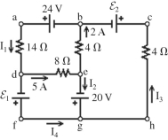
(Multiple Choice)
4.7/5 (35)
For the circuit shown in the figure, R1 = 5.6 Ω, R2 = 5.6 Ω, R3 = 14 Ω, and ε = 6.0 V, and the battery is ideal.
(a)What is the equivalent resistance across the battery?
(b)Find the current through each resistor. 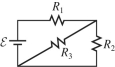
(Essay)
4.9/5 (34)
For the circuit shown in the figure, V = 60 V, C = 20 µF, R = 0.10 MΩ, and the battery is ideal. Initially the switch S is open and the capacitor is uncharged. The switch is then closed at time t = 0.00 s. What is the charge on the capacitor 8.0 s after closing the switch? 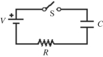
(Multiple Choice)
4.9/5 (42)
A 5-µF, a 7-µF, and an unknown capacitor CX are connected in parallel between points a and b as shown in the figure. What do you know about the equivalent capacitance Cab between a and b? (There could be more than one correct choice.) 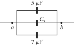
(Multiple Choice)
4.9/5 (32)
Five 2.0-Ω resistors are connected as shown in the figure. What is the equivalent resistance of this combination between points a and b? 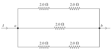
(Multiple Choice)
4.8/5 (39)
If V = 20 V and the battery is ideal, what is the current through R3 in the figure? 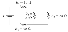
(Multiple Choice)
4.8/5 (33)
A 22-A current flows into a parallel combination of 4.0-Ω, 6.0-Ω, and 12-Ω resistors. What current flows through the 12-Ω resistor?
(Multiple Choice)
4.9/5 (40)
The capacitor shown in the circuit in the figure is initially uncharged when the switch S is suddenly closed, and the battery is ideal. After one time constant has gone by, find (a)the current through the resistor and (b)the charge on the capacitor. Assume that the numbers shown are all accurate to two significant figures. 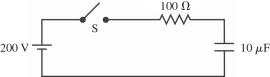
(Short Answer)
5.0/5 (29)
The capacitive network shown in the figure is assembled with initially uncharged capacitors. Assume that all the quantities in the figure are accurate to two significant figures. The switch S in the network is kept open throughout. What is the total energy stored in the seven capacitors? 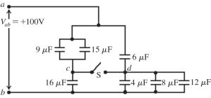
(Multiple Choice)
4.9/5 (44)
Filters
- Essay(0)
- Multiple Choice(0)
- Short Answer(0)
- True False(0)
- Matching(0)