Exam 23: Circuits
Exam 1: Representing Motion113 Questions
Exam 2: Motion in One Dimension172 Questions
Exam 3: Vectors and Motion in Two Dimensions180 Questions
Exam 4: Forces and Newtons Laws of Motion64 Questions
Exam 5: Applying Newtons Laws82 Questions
Exam 6: Gravity96 Questions
Exam 7: Rotational Motion95 Questions
Exam 8: Equilibrium Ad Elasticity72 Questions
Exam 9: Momentum103 Questions
Exam 10: Energy and Work219 Questions
Exam 11: Using Energy106 Questions
Exam 12: Thermal Properties of Matter220 Questions
Exam 13: Fluids112 Questions
Exam 14: Oscillations105 Questions
Exam 15: Traveling Waves and Sound94 Questions
Exam 16: Superposition and Standing Waves66 Questions
Exam 17: Wave Optics129 Questions
Exam 18: Ray Optics154 Questions
Exam 19: Optical Instruments137 Questions
Exam 20: Electric Fields and Forces86 Questions
Exam 21: Electric Potential140 Questions
Exam 22: Current and Resistance124 Questions
Exam 23: Circuits145 Questions
Exam 24: Magnetic Fields and Forces155 Questions
Exam 25: Em Induction and Em Waves184 Questions
Exam 26: Ac Electricity122 Questions
Exam 27: Relativity125 Questions
Exam 28: Quantum Physics85 Questions
Exam 29: Atoms and Molecules105 Questions
Exam 30: Nuclear Physics175 Questions
Select questions type
A resistor, an uncharged capacitor, a dc voltage source, and an open switch are all connected in series. The switch is closed at time t = 0 s. Which one of the following is a correct statement about the circuit?
(Multiple Choice)
4.7/5  (35)
(35)
Four resistors are connected across an ideal dc battery with voltage V as shown in the figure. Assume that all quantities shown are accurate to two significant figures. If the total current through this circuit is I = 2.0 A, what is the current through the 4.0-Ω resistor? 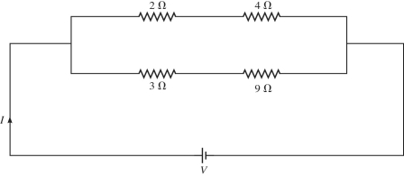
(Multiple Choice)
4.9/5 (36)
What is the magnitude of the potential difference between points C and D for the circuit shown in the figure? The battery is ideal, and all the numbers are accurate to two significant figures. 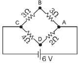
(Multiple Choice)
4.7/5 (33)
In the circuit shown in the figure, R1 = 10 Ω, R2 = 12 Ω, R3 = 20 Ω, V1 = 1.0 V, V2 = 7.0 V, and the batteries are both ideal. What is the current through R1? 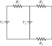
(Multiple Choice)
4.9/5 (45)
A 9-V battery is hooked up to two resistors in series. One has a resistance of 5 Ω, and the other has a resistance of 10 Ω. Several locations along the circuit are marked with letters, as shown in the figure. Through which resistor is energy being dissipated at the higher rate? 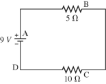
(Multiple Choice)
4.8/5 (33)
Filters
- Essay(0)
- Multiple Choice(0)
- Short Answer(0)
- True False(0)
- Matching(0)