Exam 23: Circuits
Exam 1: Representing Motion113 Questions
Exam 2: Motion in One Dimension172 Questions
Exam 3: Vectors and Motion in Two Dimensions180 Questions
Exam 4: Forces and Newtons Laws of Motion64 Questions
Exam 5: Applying Newtons Laws82 Questions
Exam 6: Gravity96 Questions
Exam 7: Rotational Motion95 Questions
Exam 8: Equilibrium Ad Elasticity72 Questions
Exam 9: Momentum103 Questions
Exam 10: Energy and Work219 Questions
Exam 11: Using Energy106 Questions
Exam 12: Thermal Properties of Matter220 Questions
Exam 13: Fluids112 Questions
Exam 14: Oscillations105 Questions
Exam 15: Traveling Waves and Sound94 Questions
Exam 16: Superposition and Standing Waves66 Questions
Exam 17: Wave Optics129 Questions
Exam 18: Ray Optics154 Questions
Exam 19: Optical Instruments137 Questions
Exam 20: Electric Fields and Forces86 Questions
Exam 21: Electric Potential140 Questions
Exam 22: Current and Resistance124 Questions
Exam 23: Circuits145 Questions
Exam 24: Magnetic Fields and Forces155 Questions
Exam 25: Em Induction and Em Waves184 Questions
Exam 26: Ac Electricity122 Questions
Exam 27: Relativity125 Questions
Exam 28: Quantum Physics85 Questions
Exam 29: Atoms and Molecules105 Questions
Exam 30: Nuclear Physics175 Questions
Select questions type
A 5.0-μF capacitor and a 7.0-μF capacitor are connected in series across an 8.0-V potential source. What is the potential difference across the 5.0-μF capacitor?
(Multiple Choice)
4.8/5  (37)
(37)
For the circuit shown in the figure, both batteries are ideal. What current flows in the solid wire connecting the upper left and lower left corners of the circuit? 
(Multiple Choice)
4.8/5 (40)
Four resistors are connected across an ideal dc source of V = 8.0 V, as shown in the figure. Assume all resistances shown are accurate to two significant figures. What is the current through the 9.0-Ω resistor? 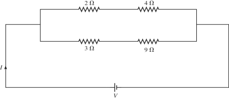
(Multiple Choice)
4.9/5 (34)
Four resistors are connected across an ideal dc battery with voltage V, as shown in the figure. If the total current in this circuit is I = 1 A, what is the value of the voltage V? 
(Multiple Choice)
4.7/5 (35)
A resistor with a resistance of 360 ? is in a series circuit with a capacitor of capacitance 7.3 × 10⁻⁶ F. What capacitance must be placed in parallel with the original capacitance to change the capacitive time constant of the combination to three times its original value?
(Short Answer)
4.7/5 (36)
The network shown is assembled with uncharged capacitors X , Y, and Z, with and The switches S1 and S2 are initially open, and a potential difference Vab = 120 V is applied between points a and b. After the network is assembled, switch S1 is then closed, but switch S2 is kept open. How much energy is finally stored in capacitor X? 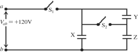
(Multiple Choice)
4.9/5 (41)
When two or more different capacitors are connected in parallel across a potential source (battery), which of the following statements must be true? (There could be more than one correct choice.)
(Multiple Choice)
4.7/5 (33)
Three capacitors of capacitance 5.00 ?F, 10.0 ?F, and 50.0 ?F are connected in series across a 12.0-V potential difference (a battery).
(a)How much charge is stored in the 5.00-?F capacitor?
(b)What is the potential difference across the 10.0-µF capacitor?
(Short Answer)
4.9/5 (38)
In the circuit shown in the figure, R1 = 60 Ω, R2 = 120 Ω, R3 = 180 Ω, V1 = 3.0 V, V2 = 6.0 V, and the batteries are both ideal. What is the current through R1? 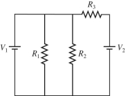
(Multiple Choice)
4.9/5 (42)
A multiloop circuit is shown in the figure. Find the current I1 if the batteries are ideal. (It is not necessary to solve the entire circuit.) 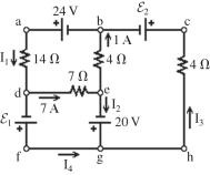
(Multiple Choice)
4.8/5 (33)
A 4.0-µF capacitor and an 8.0-µF capacitor are connected together. What is the equivalent capacitance of the combination if they are connected (a)in series or (b)in parallel?
(Short Answer)
4.8/5 (38)
Two 4.0-Ω resistors are connected in parallel, and this combination is connected in series with 3.0 Ω. What is the equivalent resistance of this system?
(Multiple Choice)
4.9/5 (34)
Three resistors with resistances of 2.0 Ω, 6.0 Ω, and 12 Ω are connected across an ideal dc voltage source V = 2.0 V, as shown in the figure. What is the total current I in this circuit? 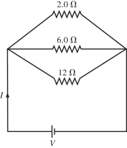
(Multiple Choice)
4.9/5 (39)
Identical ideal batteries are connected in different arrangements to the same light bulb, as shown in the figure. For which arrangement will the bulb shine the brightest? 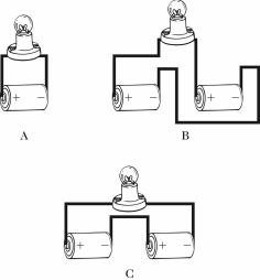
(Multiple Choice)
4.9/5 (37)
What is the magnitude of the potential difference between points B and C for the circuit shown in the figure? The battery is ideal, and all the numbers are accurate to two significant figures. 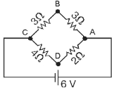
(Multiple Choice)
4.8/5 (32)
A 2.0-μF capacitor is charged to 12 V and then discharged through a 4.0-MΩ resistor. How long will it take for the voltage across the capacitor to drop to 3.0 V?
(Multiple Choice)
4.9/5 (52)
Four resistors having resistances of 20 Ω, 40 Ω, 60 Ω, and 80 Ω are connected in series across an ideal dc voltage source. If the current through this circuit is 0.50 A, what is the voltage of the voltage source?
(Multiple Choice)
4.9/5 (34)
For the circuit shown in the figure, write the Kirchhoff current equation for the node labeled A. Notice the directions of the currents! 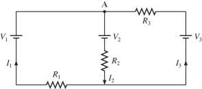
(Essay)
5.0/5 (41)
Filters
- Essay(0)
- Multiple Choice(0)
- Short Answer(0)
- True False(0)
- Matching(0)