Exam 5: Combinational Logic Analysis
Exam 1: Introductory Concepts75 Questions
Exam 2: Number Systems, Operations, and Codes49 Questions
Exam 3: Logic Gates56 Questions
Exam 4: Boolean Algebra and Logic Simplification46 Questions
Exam 5: Combinational Logic Analysis38 Questions
Exam 6: Functions of Combinational Logic46 Questions
Exam 7: Latches, Flip-Flops, and Timers38 Questions
Exam 8: Shift Registers40 Questions
Exam 9: Counters50 Questions
Exam 10: Programmable Logic30 Questions
Exam 11: Data Storage49 Questions
Exam 12: Signal Conversion and Processing46 Questions
Exam 13: Data Transmission99 Questions
Exam 14: Data Processing and Control127 Questions
Exam 15: Integrated Circuit Technologies40 Questions
Select questions type
The NAND gate is an example of combinational logic.
Free
(True/False)
4.9/5  (31)
(31)
Correct Answer: Verified
True
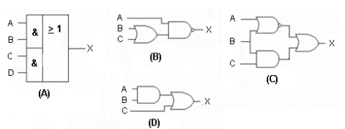
Which figure below represents AND- OR logic?
Free
(Multiple Choice)
4.7/5 (24)
Correct Answer:Verified
A
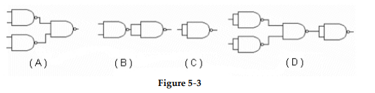 -Which circuit in Figure 5- 3 represents the NAND implementation of an inverter?
Free
(Multiple Choice)
5.0/5 (33)
Correct Answer:Verified
C
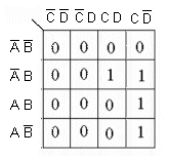
The Karnaugh map below represents the expression, X = ACD + AB(CD + BC).
(True/False)
4.9/5 (33)
The NAND gate is referred to as a "universal" gate, because it_________.
(Multiple Choice)
4.9/5 (31)
How many gates, including inverters, are required to implement the equation,  as it is written?
(Multiple Choice)
4.9/5 (27)
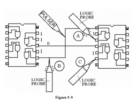 -Based on the indications of probe C in Figure 5- 5, what, if anything, is wrong with the circuit?
(Multiple Choice)
4.7/5 (37)
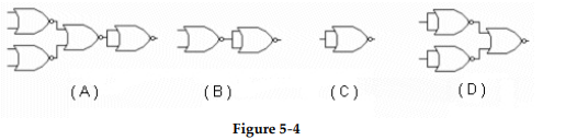 -Which circuit in Figure 5- 4 represents the NOR implementation of an OR gate?
(Multiple Choice)
4.9/5 (32)
-Which circuit in Figure 5- 3 represents the NAND implementation of an AND- OR function?
(Multiple Choice)
4.7/5 (29)
Which of the figures is the correct NAND logic implementation of the expression, 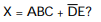
(Multiple Choice)
4.7/5 (35)
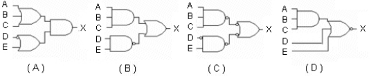
This circuit is an example of the implementation of AND- OR- INVERT logic.
(True/False)
4.9/5 (35)
The output of a gate has an internal short. A current tracer will ________.
(Multiple Choice)
4.7/5 (32)
-Based on the indications of probe A in Figure 5- 5, what, if anything, is wrong with the circuit?
(Multiple Choice)
4.8/5 (36)
How many gates, including inverters, are required to implement the equation, 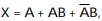 after it is simplified using Boolean algebra?
(Multiple Choice)
4.9/5 (34)
-Which circuit in Figure 5- 4 represents the NOR implementation of an inverter?
(Multiple Choice)
4.8/5 (36)
What is the indication of a short to ground in the output of a driving gate?
(Multiple Choice)
4.8/5 (40)
When the inverted output of one gate is connected to the inverted input of another gate, __________.
(Multiple Choice)
4.8/5 (37)
Filters
- Essay(0)
- Multiple Choice(0)
- Short Answer(0)
- True False(0)
- Matching(0)