Exam 33: Electromagnetic Induction
Exam 1: Concepts of Motion52 Questions
Exam 2: Kinematics in One Dimension59 Questions
Exam 3: Vectors and Coordinate Systems33 Questions
Exam 4: Kinematics in Two Dimensions50 Questions
Exam 5: Force and Motion31 Questions
Exam 6: Dynamics I: Motion Along a Line46 Questions
Exam 7: Newtons Third Law43 Questions
Exam 8: Dynamics Ii: Motion in a Plane20 Questions
Exam 9: Impulse and Momentum20 Questions
Exam 10: Energy43 Questions
Exam 11: Work100 Questions
Exam 12: Rotation of a Rigid Body113 Questions
Exam 13: Newtons Theory of Gravity50 Questions
Exam 14: Oscillations49 Questions
Exam 15: Fluids and Elasticity72 Questions
Exam 16: A Macroscopic Description of Matter29 Questions
Exam 17: Work, Heat, and the First Law of Thermodynamics98 Questions
Exam 18: The Micromacro Connection39 Questions
Exam 19: Heat Engines and Refrigerators50 Questions
Exam 20: Traveling Waves49 Questions
Exam 21: Superpositions64 Questions
Exam 22: Wave Optics51 Questions
Exam 23: Ray Optics63 Questions
Exam 24: Optical Instruments49 Questions
Exam 25: Electric Charges and Forces26 Questions
Exam 26: The Electric Field32 Questions
Exam 27: Gausss Law41 Questions
Exam 28: The Electric Potential40 Questions
Exam 29: Potential and Field57 Questions
Exam 30: Current and Resistance32 Questions
Exam 31: Fundamentals of Circuits68 Questions
Exam 32: The Magnetic Field87 Questions
Exam 33: Electromagnetic Induction66 Questions
Exam 34: Electromagnetic Fields and Waves52 Questions
Exam 35: Ac Circuits46 Questions
Exam 36: Relativity49 Questions
Exam 37: The Foundations of Modern Physics8 Questions
Exam 38: Quantization54 Questions
Exam 39: Wave Functions and Uncertainty18 Questions
Exam 40: One-Dimensional Quantum Mechanics32 Questions
Exam 41: Atomic Physics39 Questions
Exam 42: Nuclear Physics65 Questions
Select questions type
In the figure, two parallel wires carry currents of magnitude I in opposite directions. A rectangular loop is midway between the wires. The current I is decreasing with time. The induced current through the resistor R is 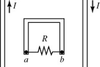
Free
(Multiple Choice)
4.8/5  (35)
(35)
Correct Answer: Verified
A
Suppose that you wish to construct a simple ac generator having an output of 12 V maximum when rotated at 60 Hz. A uniform magnetic field of 0.050 T is available. If the area of the rotating coil is 100 cm2, how many turns do you need?
Free
(Multiple Choice)
5.0/5 (31)
Correct Answer:Verified
D
A bar magnet is held vertically with its upper end a little bit below the center of a horizontal metal ring. The upper end of the magnet is its north pole, as shown in the figure. The bar magnet is now dropped. An observer views the ring from above its center. To this observer, how will the induced current in the ring behave as the magnet falls? 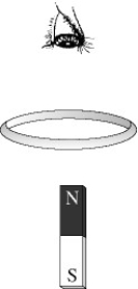
Free
(Multiple Choice)
4.8/5 (29)
Correct Answer:Verified
D
A series LR circuit contains an emf source of 14V having no internal resistance, a resistor, a 34 H inductor having no appreciable resistance, and a switch. If the emf across the inductor is 80% of its maximum value 4.0 s after the switch is closed, what is the resistance of the resistor?
(Multiple Choice)
4.8/5 (30)
In the figure, a straight wire carries a current I. The wire passes through the center of a toroidal coil. If the current in the wire is quickly reduced to zero, the induced current through the resistor R is 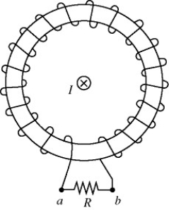
(Multiple Choice)
4.7/5 (33)
In the figure, a C-shaped conductor is in a uniform magnetic field B, which is increasing. The polarity of the induced emf in terminals X and Y is 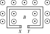
(Multiple Choice)
4.8/5 (40)
Wire is wound on a square frame, 30 cm by 30 cm, to form a coil of 7 turns. The frame is mounted on a horizontal shaft through its center (perpendicular to the plane of the diagram), as shown in the figure. The coil is in clockwise rotation, with a period of 0.060 s. A uniform, horizontal, magnetic field of magnitude 0.40 T is present. At a given instant, the plane of the coil forms a 60° angle with the horizontal, as shown. At that instant, what is the magnitude of the emf induced in the coil? 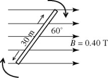
(Multiple Choice)
4.7/5 (32)
A capacitor is charging in a simple RC circuit with a dc battery. Which one of the following statements about this capacitor is accurate?
(Multiple Choice)
4.8/5 (36)
A 45-mH ideal inductor is connected in series with a 60-Ω resistor through an ideal 15-V DC power supply and an open switch. If the switch is closed at time t = 0 s, what is the current 7.0 ms later?
(Multiple Choice)
4.8/5 (35)
The figure shows a bar magnet moving vertically upward toward a horizontal coil. The poles of the bar magnets are labeled X and Y. As the bar magnet approaches the coil it induces an electric current in the direction indicated on the figure (counter-clockwise as viewed from above). What are the correct polarities of the magnet? 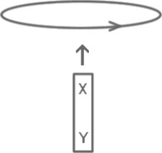
(Multiple Choice)
4.7/5 (33)
A circular coil of radius 5.0 cm and resistance 0.20 Ω is placed in a uniform magnetic field perpendicular to the plane of the coil. The magnitude of the field changes with time according to B = 0.50e-20t T. What is the magnitude of the current induced in the coil at the time t = 2.0 s?
(Multiple Choice)
4.9/5 (31)
In an LC circuit containing a 40-mH ideal inductor and a 1.2-mF capacitor, the maximum charge on the capacitor is 45 mC during the oscillations. What is the maximum current through the inductor during the oscillations?
(Multiple Choice)
4.8/5 (33)
In the figure, a bar magnet moves away from the solenoid. The induced current through the resistor R is 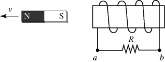
(Multiple Choice)
4.7/5 (37)
A large magnetic flux change through a coil must induce a greater emf in the coil than a small flux change.
(True/False)
4.9/5 (25)
A transformer changes the 10,000 V power line to 120 V. If the primary coil contains 750 turns, how many turns are on the secondary?
(Multiple Choice)
4.8/5 (41)
A 2.0-m long conducting wire is formed into a square and placed in the horizontal xy-plane. A uniform magnetic field is oriented 30.0∘ above the horizontal with a strength of 9.0 T. What is the magnetic flux through the square?
(Multiple Choice)
4.8/5 (31)
In the figure, a copper bar is in contact with a pair of parallel metal rails and is in motion with velocity ν. A uniform magnetic field is present pointing downward, as shown. The bar, the rails, and the resistor R are all in the same plane. The induced current through the resistor R is 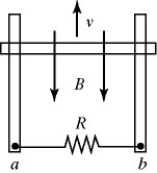
(Multiple Choice)
4.9/5 (31)
In the figure, two solenoids are approaching each other with speed v as shown. The induced current through the resistor R is 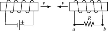
(Multiple Choice)
4.9/5 (40)
An ideal solenoid is 18.5 cm long, has a circular cross-section 2.20 cm in diameter, and contains 545 equally spaced thin windings. This solenoid is connected in a series circuit with an open switch, a 15.0-Ω resistor, and a battery of internal resistance 5.00 Ω and open-circuit terminal voltage of 25.0 V. (μ0 = 4π × 10-7 T ∙ m/A)
(a) What is the maximum amount of energy that the solenoid will store after closing the switch?
(b) How long after closing the switch will it take for the stored energy in the solenoid to reach one-half of its maximum value?
(Essay)
4.8/5 (44)
In the figure, a straight wire carries a steady current I perpendicular to the plane of the page. A bar is in contact with a pair of circular rails, and rotates about the straight wire. The direction of the induced current through the resistor R is 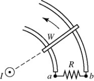
(Multiple Choice)
4.8/5 (38)
Filters
- Essay(0)
- Multiple Choice(0)
- Short Answer(0)
- True False(0)
- Matching(0)