Exam 26: Direct-Current Circuits
Exam 1: Units,physical Quantities,and Vectors107 Questions
Exam 2: Motion Along a Straight Line59 Questions
Exam 3: Motion in Two or Three Dimensions50 Questions
Exam 4: Newtons Laws of Motion44 Questions
Exam 5: Applying Newtons Laws95 Questions
Exam 6: Work and Kinetic Energy54 Questions
Exam 7: Potential Energy and Energy Conservation55 Questions
Exam 8: Momentum,impulse,and Collisions50 Questions
Exam 9: Rotation of Rigid Bodies26 Questions
Exam 10: Dynamics of Rotational Motion49 Questions
Exam 11: Equilibrium and Elasticity50 Questions
Exam 12: Fluid Mechanics50 Questions
Exam 13: Gravitation50 Questions
Exam 14: Periodic Motion50 Questions
Exam 15: Mechanical Waves44 Questions
Exam 16: Sound and Hearing65 Questions
Exam 17: Temperature and Heat63 Questions
Exam 18: Thermal Properties of Matter58 Questions
Exam 19: The First Law of Thermodynamics52 Questions
Exam 20: The Second Law of Thermodynamics50 Questions
Exam 21: Electric Charge and Electric Field60 Questions
Exam 22: Gausss Law41 Questions
Exam 23: Electric Potential55 Questions
Exam 24: Capacitance and Dielectrics52 Questions
Exam 25: Current,resistance,and Electromotive Force55 Questions
Exam 26: Direct-Current Circuits53 Questions
Exam 27: Magnetic Field and Magnetic Forces42 Questions
Exam 28: Sources of Magnetic Field52 Questions
Exam 29: Electromagnetic Induction39 Questions
Exam 30: Inductance27 Questions
Exam 31: Alternating Current50 Questions
Exam 32: Electromagnetic Waves47 Questions
Exam 33: The Nature and Propagation of Light28 Questions
Exam 34: Geometric Optics81 Questions
Exam 35: Interference33 Questions
Exam 36: Diffraction49 Questions
Exam 37: Relativity51 Questions
Exam 38: Photons: Light Waves Behaving As Particles38 Questions
Exam 39: Particles Behaving As Waves52 Questions
Exam 40: Quantum Mechanics43 Questions
Exam 41: Atomic Structure53 Questions
Exam 42: Molecules and Condensed Matter31 Questions
Exam 43: Nuclear Physics90 Questions
Exam 44: Particle Physics and Cosmology54 Questions
Select questions type
For the circuit shown in the figure,what current does the ideal ammeter read? 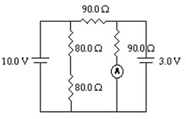
(Multiple Choice)
4.8/5  (42)
(42)
A galvanometer coil having a resistance of 20 Ω and a full-scale deflection at 1.0 mA is connected in series with a 4980 Ω resistance to build a voltmeter.What is the maximum voltage that this voltmeter can read?
(Multiple Choice)
4.8/5 (44)
When four identical resistors are connected to an ideal battery of voltage V = 10 V as shown in the figure,the current I is equal to 0.20 A.What is the value of the resistance R of the resistors? 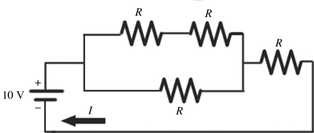
(Multiple Choice)
4.8/5 (37)
In the circuit shown in the figure,an ideal ohmmeter is connected across ab with the switch S open.All the connecting leads have negligible resistance.The reading of the ohmmeter will be closest to 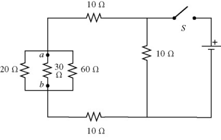
(Multiple Choice)
4.8/5 (36)
For the circuit shown in the figure,all quantities are accurate to 3 significant figures.What is the power dissipated in the 2-Ω resistor? 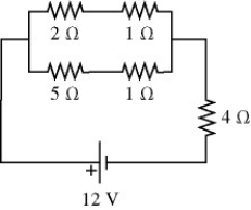
(Multiple Choice)
4.9/5 (41)
An RC circuit is connected across an ideal DC voltage source through an open switch.The switch is closed at time t = 0 s.Which of the following statements regarding the circuit are correct? (There may be more than one correct choice.)
(Multiple Choice)
5.0/5 (33)
A light bulb is connected in the circuit shown in the figure with the switch S open.All the connecting leads have no appreciable resistance and the battery has no internal resistance.When we close the switch,which statements below accurately describe the behavior of the circuit? (There may be more than one correct choice.) 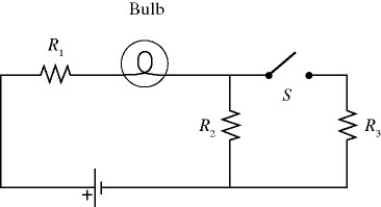
(Multiple Choice)
4.9/5 (33)
A multiloop circuit is shown in the figure.It is not necessary to solve the entire circuit.Compared to the polarity shown in the figure,the emf ε1 is closest to 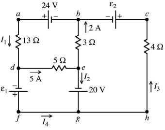
(Multiple Choice)
4.9/5 (30)
For the circuit shown in the figure,the switch S is initially open and the capacitor voltage is 80 V.The switch is then closed at time t = 0.What is the charge on the capacitor when the current in the circuit is 33 μA? 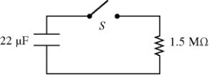
(Multiple Choice)
4.8/5 (35)
A light bulb is connected in the circuit shown in the figure with the switch S open and the capacitor uncharged.The battery has no appreciable internal resistance.Which one of the following graphs best describes the brightness B of the bulb as a function of time t after closing the switch? 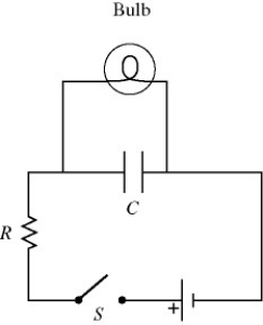
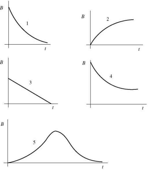
(Multiple Choice)
4.7/5 (45)
A galvanometer G has an internal resistance rg.A VOLTMETER is constructed by incorporating the galvanometer and an additional resistance Rs.Which one of the figures below is the most appropriate circuit diagram for the voltmeter? 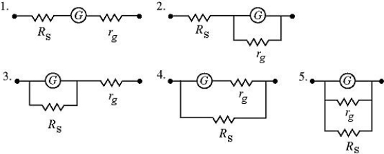
(Multiple Choice)
4.8/5 (33)
When a 20.0-ohm resistor is connected across the terminals of a 12.0-V battery,the voltage across the terminals of the battery falls by 0.300 V.What is the internal resistance of this battery?
(Multiple Choice)
4.9/5 (34)
Two unknown resistors are connected together.When they are connected in series their equivalent resistance is 15 Ω.When they are connected in parallel,their equivalent resistance is 3.3 Ω.What are the resistances of these resistors?
(Short Answer)
4.9/5 (44)
Filters
- Essay(0)
- Multiple Choice(0)
- Short Answer(0)
- True False(0)
- Matching(0)