Exam 31: Fundamentals of Circuits
Exam 1: Concepts of Motion52 Questions
Exam 2: Kinematics in One Dimension59 Questions
Exam 3: Vectors and Coordinate Systems33 Questions
Exam 4: Kinematics in Two Dimensions50 Questions
Exam 5: Force and Motion31 Questions
Exam 6: Dynamics I: Motion Along a Line46 Questions
Exam 7: Newtons Third Law43 Questions
Exam 8: Dynamics Ii: Motion in a Plane20 Questions
Exam 9: Impulse and Momentum20 Questions
Exam 10: Energy43 Questions
Exam 11: Work100 Questions
Exam 12: Rotation of a Rigid Body113 Questions
Exam 13: Newtons Theory of Gravity50 Questions
Exam 14: Oscillations49 Questions
Exam 15: Fluids and Elasticity72 Questions
Exam 16: A Macroscopic Description of Matter29 Questions
Exam 17: Work, Heat, and the First Law of Thermodynamics98 Questions
Exam 18: The Micromacro Connection39 Questions
Exam 19: Heat Engines and Refrigerators50 Questions
Exam 20: Traveling Waves49 Questions
Exam 21: Superpositions64 Questions
Exam 22: Wave Optics51 Questions
Exam 23: Ray Optics63 Questions
Exam 24: Optical Instruments49 Questions
Exam 25: Electric Charges and Forces26 Questions
Exam 26: The Electric Field32 Questions
Exam 27: Gausss Law41 Questions
Exam 28: The Electric Potential40 Questions
Exam 29: Potential and Field57 Questions
Exam 30: Current and Resistance32 Questions
Exam 31: Fundamentals of Circuits68 Questions
Exam 32: The Magnetic Field87 Questions
Exam 33: Electromagnetic Induction66 Questions
Exam 34: Electromagnetic Fields and Waves52 Questions
Exam 35: Ac Circuits46 Questions
Exam 36: Relativity49 Questions
Exam 37: The Foundations of Modern Physics8 Questions
Exam 38: Quantization54 Questions
Exam 39: Wave Functions and Uncertainty18 Questions
Exam 40: One-Dimensional Quantum Mechanics32 Questions
Exam 41: Atomic Physics39 Questions
Exam 42: Nuclear Physics65 Questions
Select questions type
For the circuit shown in the figure, the current in the 8-Ω resistor is 0.50 A, and all quantities are accurate to 2 significant figures. What is the current in the 2-Ω resistor? 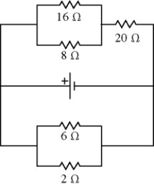
(Multiple Choice)
4.9/5  (32)
(32)
A multiloop circuit is shown in the figure. It is not necessary to solve the entire circuit. Compared to the polarity shown in the figure, the emf ε1 is closest to 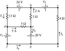
(Multiple Choice)
4.8/5 (44)
A galvanometer with a resistance of 40.0 Ω deflects full scale at a current of 2.0 mA. What resistance should be used with this galvanometer in order to construct a voltmeter that can read a maximum of 50 V?
(Multiple Choice)
4.9/5 (38)
For the circuit shown in the figure, determine the current in
(a) the 1.0-Ω resistor.
(b) the 3.0-Ω resistor.
(c) the 4.0-Ω resistor. 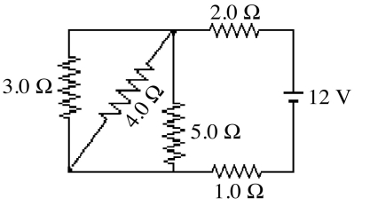
(Essay)
4.9/5 (31)
The figure shows three identical lightbulbs connected to a battery having a constant voltage across its terminals. What happens to the brightness of lightbulb 1 when the switch S is closed? 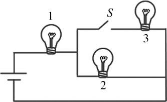
(Multiple Choice)
4.8/5 (32)
A multiloop circuit is shown in the figure. Some circuit quantities are not labeled. It is not necessary to solve the entire circuit. The current I2 is closest to 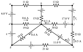
(Multiple Choice)
4.9/5 (30)
The emf and the internal resistance of a battery are shown in the figure. If a current of 7.8 A is established through the battery from b to a, what is the terminal voltage Vab of the battery? 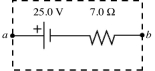
(Multiple Choice)
4.8/5 (39)
For the circuit shown in the figure, determine the current in
(a) the 7.0-Ω resistor.
(b) the 8.0-Ω resistor.
(c) the 4.0-Ω resistor. 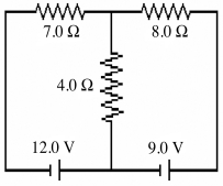
(Essay)
4.8/5 (40)
A galvanometer has a coil with a resistance of 24.0 Ω, and a current of 180 μA causes it to deflect full scale. If this galvanometer is to be used to construct an ammeter that can read up to 10.0 A, what shunt resistor is required?
(Multiple Choice)
4.8/5 (40)
In the figure a current of 6.0 A is drawn from the battery. What is the terminal voltage Vab of the battery? 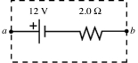
(Multiple Choice)
4.9/5 (38)
A 6.0-μF capacitor is connected in series with= 5.0 MΩ resistor, and this combination is connected across an ideal 15-V DC battery. What is the current in the circuit when the capacitor has reached 20% of its maximum charge?
(Multiple Choice)
4.8/5 (48)
A galvanometer has an internal resistance of 100 Ω and deflects full-scale at a current of 2.00 mA. What size resistor should be added to it to convert it to a millivoltmeter capable of reading up to 400 mV, and how should this resistor be connected to the galvanometer?
(Multiple Choice)
4.7/5 (40)
Three resistors having resistances of 4.0 Ω, 6.0 Ω, and 10.0 Ω are connected in parallel. If the combination is connected in series with an ideal 12-V battery and a 2.0-Ω resistor, what is the current through the 10.0-Ω resistor?
(Multiple Choice)
4.8/5 (41)
A multiloop circuit is shown in the figure. Some circuit quantities are not labeled. It is not necessary to solve the entire circuit. The emf ε is closest to 
(Multiple Choice)
4.7/5 (47)
When four identical resistors are connected to an ideal battery of voltage V = 10 V as shown in the figure, the current I is equal to 0.20 A. What is the value of the resistance R of the resistors? 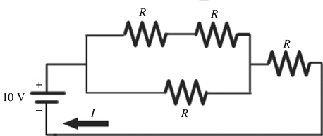
(Multiple Choice)
4.9/5 (43)
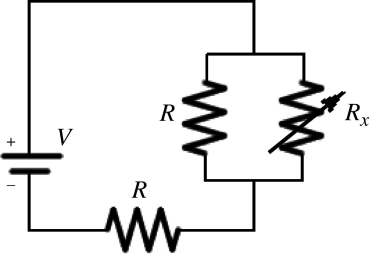
Two identical resistors of resistance R = 24 Ω and a variable resistor Rx are connected to an ideal battery of voltage V as shown in the figure. What should be the value of the variable resistance Rx to make the voltage across the two parallel resistors equal to  .
. 
(Multiple Choice)
4.9/5 (37)
A light bulb is connected to a 110-V source. What is the resistance of this bulb if it is a 100-W bulb?
(Multiple Choice)
4.9/5 (35)
In the circuit shown in the figure, an ideal ohmmeter is connected across ab with the switch S open. All the connecting leads have negligible resistance. The reading of the ohmmeter will be closest to 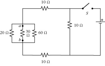
(Multiple Choice)
4.8/5 (39)
When a 100-Ω resistor is connected across the terminals of a battery of emf ε and internal resistance r, the battery delivers 0.794 W of power to the 100-Ω resistor. When the 100-Ω resistor is replaced by a 200-Ω resistor, the battery delivers 0.401 W of power to the 200-Ω resistor. What are the emf and internal resistance of the battery?
(Multiple Choice)
4.8/5 (30)
Consider the circuit shown in the figure. Note that two currents are shown. Calculate the emfs ε1 and ε3. 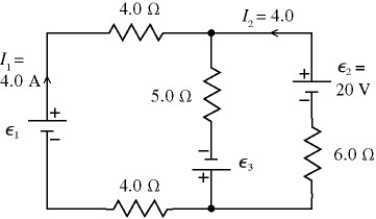
(Essay)
4.9/5 (40)
Filters
- Essay(0)
- Multiple Choice(0)
- Short Answer(0)
- True False(0)
- Matching(0)