Correct Answer: Verified
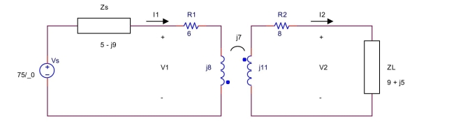
 −Vs+ZsI1+V1=0−V2+ZLI2=0 V1=R1I1+ZL1I1+ZMI2 V2=−ZMI1−R2I2−ZL2I2 Solving these equations, we obtain I1=5.8761∠11.0143∘AI2=1.7619∠−122.25∘AV1=58.6818∠52.0883∘VV2=18.1402∠−93.1954∘V clear all;
ZL1=8j;ZL2=11j;ZM=7j;R1=6;R2=8;Zs=5−9j;ZL=9+5j;ZMM=abs(ZM) ;
Vm=75;phi=0 ;
Vs=P2Rd(Vm,phi)
syms I1 I2 V1 V2
[II2 V1 V2]=solve(−Vs+Zs∗I1+V1,−V2+ZL∗I2,…
V1==R1 * I1+ZL1 * I1+ZM∗I2,…
V2==−R2⋆I2−ZM∗I1−ZL2⋆I2,…
I1,I2, V1, V2) ;
I 1p=R2P(I1) ;
I2p=R2P(I2);
V1p=R2P(Vl); V2p=R2P(V2) ;
V2p=R2P(V2) ;
I 1=vpa(I1,6) I 1p=vpa(I1p,7)
I2 = vpa (I2,6)
I 2p=vpa (I2p,7)
V1=vpa(V1,6)
V1p=vpa(V1p,7)
V2=vpa(V2,6)
V2p =vpa(V2p,7)
VO=I2∗ZL
Vop = R2P (Vo)
Vop =vpa(Vop,7)

 (24)
(24)