Exam 25: Direct-Current Circuits
Exam 1: Units, Physical Quantities, and Vectors107 Questions
Exam 2: Motion Along a Straight Line59 Questions
Exam 3: Motion in Two or Three Dimensions50 Questions
Exam 4: Newtons Laws of Motion44 Questions
Exam 5: Applying Newtons Laws95 Questions
Exam 6: Work and Kinetic Energy54 Questions
Exam 7: Potential Energy and Energy Conservation55 Questions
Exam 8: Momentum, Impulse, and Collisions50 Questions
Exam 9: Rotation of Rigid Bodies26 Questions
Exam 10: Equilibrium and Elasticity50 Questions
Exam 11: Fluid Mechanics50 Questions
Exam 12: Gravitation50 Questions
Exam 13: Periodic Motion50 Questions
Exam 14: Mechanical Waves44 Questions
Exam 15: Sound and Hearing66 Questions
Exam 16: Temperature and Heat63 Questions
Exam 17: Thermal Properties of Matter58 Questions
Exam 18: The First Law of Thermodynamics52 Questions
Exam 19: The Second Law of Thermodynamics50 Questions
Exam 20: Electric Charge and Electric Field58 Questions
Exam 21: Gausss Law41 Questions
Exam 22: Electric Potential55 Questions
Exam 23: Capacitance and Dielectrics52 Questions
Exam 24: Current, Resistance, and Electromotive Force50 Questions
Exam 25: Direct-Current Circuits53 Questions
Exam 26: Magnetic Field and Magnetic Forces36 Questions
Exam 27: Sources of Magnetic Field51 Questions
Exam 28: Electromagnetic Induction39 Questions
Exam 29: Inductance26 Questions
Exam 30: Alternating Current49 Questions
Exam 31: Electromagnetic Waves47 Questions
Exam 32: The Nature and Propagation of Light28 Questions
Exam 33: Geometric Optics81 Questions
Exam 34: Interference33 Questions
Exam 35: Diffraction49 Questions
Exam 36: Relativity51 Questions
Exam 37: Photons: Light Waves Behaving As Particles38 Questions
Exam 38: Particles Behaving As Waves52 Questions
Exam 39: Quantum Mechanics40 Questions
Exam 40: Atomic Structure41 Questions
Exam 41: Molecules and Condensed Matter31 Questions
Exam 42: Nuclear Physics89 Questions
Exam 43: Particle Physics and Cosmology44 Questions
Select questions type
For the circuit shown in the figure, determine the current in
(a) the 1.0-Ω resistor.
(b) the 3.0-Ω resistor.
(c) the 4.0-Ω resistor. 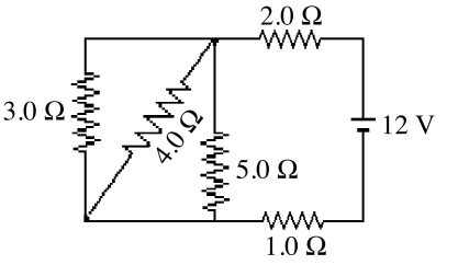
Free
(Short Answer)
4.9/5  (39)
(39)
Correct Answer: Verified
(a) 2.8 A
(b) 1.2 A
(c) 0.90 A
A resistor is made out of a long wire having a length L. Each end of the wire is attached to a terminal of a battery providing a constant voltage V0. A current I flows through the wire. If the wire were cut in half, making two wires of length L/2, and both wires were attached to the battery (the end of both wires attached to one terminal, and the other ends attached to the other terminal), what would be the total current flowing through the two wires?
Free
(Multiple Choice)
4.8/5 (35)
Correct Answer:Verified
A
A multiloop circuit is shown in the figure. Some circuit quantities are not labeled. It is not necessary to solve the entire circuit. The current I2 is closest to 
Free
(Multiple Choice)
4.9/5 (34)
Correct Answer:Verified
E
Four resistors are connected across an 8-V DC battery as shown in the figure. The current through the 9-Ω resistor is closest to 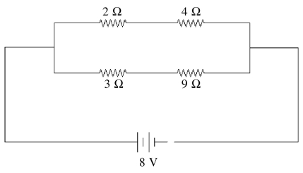
(Multiple Choice)
4.8/5 (29)
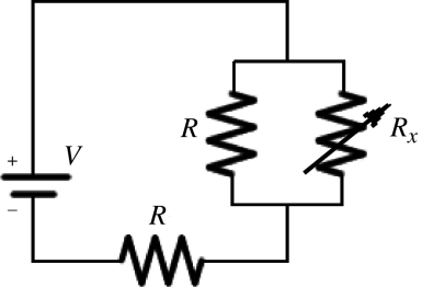
Two identical resistors of resistance R = 24 Ω and a variable resistor Rx are connected to an ideal battery of voltage V as shown in the figure. What should be the value of the variable resistance Rx to make the voltage across the two parallel resistors equal to  .
. 
(Multiple Choice)
4.8/5 (32)
Two unknown resistors are connected together. When they are connected in series their equivalent resistance is 15 Ω. When they are connected in parallel, their equivalent resistance is 3.3 Ω. What are the resistances of these resistors?
(Short Answer)
4.9/5 (35)
When a 100-Ω resistor is connected across the terminals of a battery of emf ε and internal resistance r, the battery delivers 0.794 W of power to the 100-Ω resistor. When the 100-Ω resistor is replaced by a 200-Ω resistor, the battery delivers 0.401 W of power to the 200-Ω resistor. What are the emf and internal resistance of the battery?
(Multiple Choice)
5.0/5 (37)
In the circuit shown in the figure, two 360.0-Ω resistors are connected in series with an ideal source of emf. A voltmeter with internal resistance of 6350 Ω is connected across one of the resistors and reads 3.23 V. Find the emf of the source. 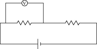
(Short Answer)
4.9/5 (41)
For the circuit shown in the figure, what is the current through resistor R1? 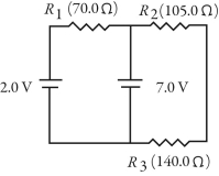
(Multiple Choice)
4.9/5 (34)
A multiloop circuit is shown in the figure. It is not necessary to solve the entire circuit. Compared to the polarity shown in the figure, the emf ε1 is closest to 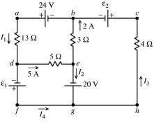
(Multiple Choice)
4.8/5 (31)
A multiloop circuit is shown in the figure. Some circuit quantities are not labeled. It is not necessary to solve the entire circuit. The current I1 is closest to 
(Multiple Choice)
4.9/5 (27)
A multiloop circuit is shown in the figure. It is not necessary to solve the entire circuit. The current I2 is closest to 
(Multiple Choice)
4.7/5 (32)
As more resistors are added in parallel across a constant voltage source, the power supplied by the source
(Multiple Choice)
4.8/5 (44)
A multiloop circuit is shown in the figure. Some circuit quantities are not labeled. It is not necessary to solve the entire circuit. The emf ε is closest to 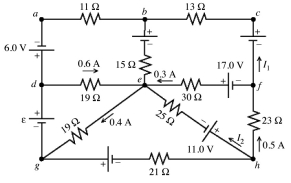
(Multiple Choice)
4.7/5 (36)
A galvanometer G has an internal resistance rg. An AMMETER is constructed by incorporating the galvanometer and an additional resistance Rs. Which one of the figures below is the most appropriate circuit diagram for the ammeter? 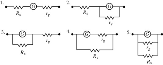
(Multiple Choice)
4.8/5 (39)
For the circuit shown in the figure, the switch S is initially open and the capacitor voltage is 80 V. The switch is then closed at time t = 0. What is the charge on the capacitor when the current in the circuit is 33 μA? 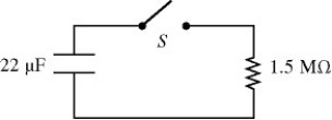
(Multiple Choice)
4.8/5 (40)
A galvanometer has a coil with a resistance of 24.0 Ω, and a current of 180 μA causes it to deflect full scale. If this galvanometer is to be used to construct an ammeter that can read up to 10.0 A, what shunt resistor is required?
(Multiple Choice)
4.9/5 (23)
A 6.0-μF capacitor is connected in series with= 5.0 MΩ resistor, and this combination is connected across an ideal 15-V DC battery. What is the current in the circuit when the capacitor has reached 20% of its maximum charge?
(Multiple Choice)
4.8/5 (33)
For the circuit shown in the figure, all quantities are accurate to 3 significant figures. What is the power dissipated in the 2-Ω resistor? 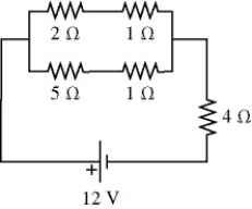
(Multiple Choice)
4.9/5 (39)
A galvanometer G has an internal resistance rg. A VOLTMETER is constructed by incorporating the galvanometer and an additional resistance Rs. Which one of the figures below is the most appropriate circuit diagram for the voltmeter? 
(Multiple Choice)
4.9/5 (33)
Filters
- Essay(0)
- Multiple Choice(0)
- Short Answer(0)
- True False(0)
- Matching(0)