Exam 25: Direct-Current Circuits
Exam 1: Units, Physical Quantities, and Vectors107 Questions
Exam 2: Motion Along a Straight Line59 Questions
Exam 3: Motion in Two or Three Dimensions50 Questions
Exam 4: Newtons Laws of Motion44 Questions
Exam 5: Applying Newtons Laws95 Questions
Exam 6: Work and Kinetic Energy54 Questions
Exam 7: Potential Energy and Energy Conservation55 Questions
Exam 8: Momentum, Impulse, and Collisions50 Questions
Exam 9: Rotation of Rigid Bodies26 Questions
Exam 10: Equilibrium and Elasticity50 Questions
Exam 11: Fluid Mechanics50 Questions
Exam 12: Gravitation50 Questions
Exam 13: Periodic Motion50 Questions
Exam 14: Mechanical Waves44 Questions
Exam 15: Sound and Hearing66 Questions
Exam 16: Temperature and Heat63 Questions
Exam 17: Thermal Properties of Matter58 Questions
Exam 18: The First Law of Thermodynamics52 Questions
Exam 19: The Second Law of Thermodynamics50 Questions
Exam 20: Electric Charge and Electric Field58 Questions
Exam 21: Gausss Law41 Questions
Exam 22: Electric Potential55 Questions
Exam 23: Capacitance and Dielectrics52 Questions
Exam 24: Current, Resistance, and Electromotive Force50 Questions
Exam 25: Direct-Current Circuits53 Questions
Exam 26: Magnetic Field and Magnetic Forces36 Questions
Exam 27: Sources of Magnetic Field51 Questions
Exam 28: Electromagnetic Induction39 Questions
Exam 29: Inductance26 Questions
Exam 30: Alternating Current49 Questions
Exam 31: Electromagnetic Waves47 Questions
Exam 32: The Nature and Propagation of Light28 Questions
Exam 33: Geometric Optics81 Questions
Exam 34: Interference33 Questions
Exam 35: Diffraction49 Questions
Exam 36: Relativity51 Questions
Exam 37: Photons: Light Waves Behaving As Particles38 Questions
Exam 38: Particles Behaving As Waves52 Questions
Exam 39: Quantum Mechanics40 Questions
Exam 40: Atomic Structure41 Questions
Exam 41: Molecules and Condensed Matter31 Questions
Exam 42: Nuclear Physics89 Questions
Exam 43: Particle Physics and Cosmology44 Questions
Select questions type
For the circuit shown in the figure, what current does the ideal ammeter read? 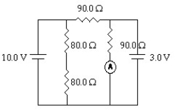
(Multiple Choice)
4.9/5  (41)
(41)
Three resistors are connected across an ideal 2.0-V DC battery as shown in the figure.
(a) At what rate does the battery supply energy to the resistors?
(b) At what rate is heat produced in the 6.0-Ω resistor? 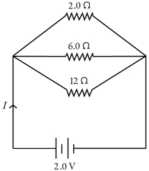
(Short Answer)
4.8/5 (35)
The figure shows three identical lightbulbs connected to a battery having a constant voltage across its terminals. What happens to the brightness of lightbulb 1 when the switch S is closed? 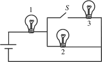
(Multiple Choice)
5.0/5 (32)
For the circuit shown in the figure, I = 0.50 A and R = 12 Ω. What is the value of the emf ε? 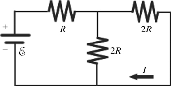
(Multiple Choice)
4.7/5 (43)
For the circuit shown in the figure, the current in the 8-Ω resistor is 0.50 A, and all quantities are accurate to 2 significant figures. What is the current in the 2-Ω resistor? 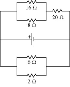
(Multiple Choice)
4.8/5 (40)
For the circuit shown in the figure, all quantities are accurate to 2 significant figures. What is the value of the current I1? 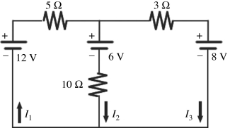
(Multiple Choice)
4.8/5 (48)
For the circuit shown in the figure, what is the current through resistor R3? 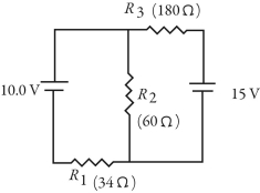
(Multiple Choice)
4.8/5 (34)
Consider the circuit shown in the figure. Note that two currents are shown. Calculate the emfs ε1 and ε3. 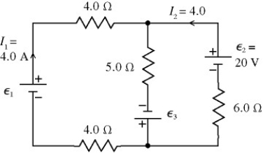
(Short Answer)
4.9/5 (34)
Three resistors having resistances of 4.0 Ω, 6.0 Ω, and 10.0 Ω are connected in parallel. If the combination is connected in series with an ideal 12-V battery and a 2.0-Ω resistor, what is the current through the 10.0-Ω resistor?
(Multiple Choice)
4.8/5 (32)
When four identical resistors are connected to an ideal battery of voltage V = 10 V as shown in the figure, the current I is equal to 0.20 A. What is the value of the resistance R of the resistors? 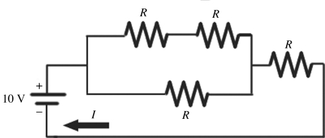
(Multiple Choice)
4.9/5 (40)
For the circuit shown in the figure, determine the current in
(a) the 7.0-Ω resistor.
(b) the 8.0-Ω resistor.
(c) the 4.0-Ω resistor. 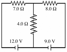
(Short Answer)
4.8/5 (34)
A 5.0-Ω resistor and a 9.0-Ω resistor are connected in parallel. A 4.0-Ω resistor is then connected in series with this parallel combination. An ideal 6.0-V battery is then connected across the series-parallel combination of the three resistors. What is the current through
(a) the 4.0-Ω resistor?
(b) the 5.0-Ω resistor?
(c) the 9.0-Ω resistor?
(Short Answer)
4.8/5 (30)
A 4.00-Ω resistor, an 8.00-Ω resistor, and a 24.0-Ω resistor are connected together.
(a) What is the maximum resistance that can be produced using all three resistors?
(b) What is the minimum resistance that can be produced using all three resistors?
(c) How would you connect these three resistors to obtain a resistance of 10.0 Ω?
(d) How would you connect these three resistors to obtain a resistance of 8.00 Ω?
(Essay)
4.8/5 (35)
In the circuit shown in the figure, four identical resistors labeled A to D are connected to a battery as shown. S1 and S2 are switches. Which of the following actions would result in the GREATEST amount of current through resistor A? 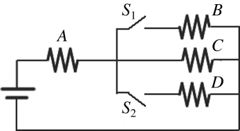
(Multiple Choice)
4.8/5 (52)
An uncharged 1.0-μF capacitor is connected in series with a 23-kΩ resistor, an ideal 7.0-V battery, and an open switch. What is the voltage across the capacitor 11 ms after closing the switch?
(Multiple Choice)
4.9/5 (39)
A galvanometer has an internal resistance of 100 Ω and deflects full-scale at 2.00 mA. What size resistor should be added to the galvanometer to convert it to a milliammeter capable of reading up to 4.00 mA, and how should this resistor be connected to the galvanometer?
(Multiple Choice)
5.0/5 (40)
What is the maximum current that can be drawn from a 1.50-V battery with an internal resistance of 0.30 ohm?
(Multiple Choice)
4.8/5 (44)
A galvanometer has an internal resistance of 100 Ω and deflects full-scale at a current of 2.00 mA. What size resistor should be added to it to convert it to a millivoltmeter capable of reading up to 400 mV, and how should this resistor be connected to the galvanometer?
(Multiple Choice)
4.9/5 (40)
A 4.0-μF capacitor that is initially uncharged is connected in series with a 4.0-kΩ resistor and an ideal 17.0-V battery. How much energy is stored in the capacitor 17 ms after the battery has been connected?
(Multiple Choice)
4.7/5 (38)
For the circuit shown in the figure, the switch S is initially open and the capacitor is uncharged. The switch is then closed at time t = 0. How many seconds after closing the switch will the energy stored in the capacitor be equal to 50.2 mJ? 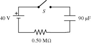
(Multiple Choice)
5.0/5 (36)
Filters
- Essay(0)
- Multiple Choice(0)
- Short Answer(0)
- True False(0)
- Matching(0)