Exam 22: Gausss Law
Exam 2: Motion Along a Straight Line55 Questions
Exam 3: Motion in Two or Three Dimensions59 Questions
Exam 4: Newtons Laws of Motion50 Questions
Exam 5: Applying Newtons Laws139 Questions
Exam 6: Work and Kinetic Energy109 Questions
Exam 7: Potential Energy and Energy Conservation50 Questions
Exam 8: Momentum, Impulse, and Collisions99 Questions
Exam 9: Rotation of Rigid Bodies26 Questions
Exam 10: Dynamics of Rotational Motion49 Questions
Exam 11: Equilibrium and Elasticity50 Questions
Exam 12: Fluid Mechanics54 Questions
Exam 13: Gravitation52 Questions
Exam 14: Periodic Motion109 Questions
Exam 15: Mechanical Waves50 Questions
Exam 16: Sound and Hearing121 Questions
Exam 17: Temperature and Heat60 Questions
Exam 18: Thermal Properties of Matter41 Questions
Exam 19: The First Law of Thermodynamics55 Questions
Exam 20: The Second Law of Thermodynamics52 Questions
Exam 21: Electric Charge and Electric Field54 Questions
Exam 22: Gausss Law54 Questions
Exam 23: Electric Potential88 Questions
Exam 24: Capacitance and Dielectrics70 Questions
Exam 25: Current, Resistance, and Electromotive Force44 Questions
Exam 26: Direct-Current Circuits51 Questions
Exam 27: Magnetic Field and Magnetic Forces105 Questions
Exam 28: Sources of Magnetic Field82 Questions
Exam 29: Electromagnetic Induction51 Questions
Exam 30: Inductance88 Questions
Exam 31: Alternating Current51 Questions
Exam 32: Electromagnetic Waves Optics53 Questions
Exam 33: The Nature and Propagation of Light31 Questions
Exam 34: Geometric Optics89 Questions
Exam 35: Interference59 Questions
Select questions type
Kirchhoff's rules: For the circuit shown in the figure, what is the current through resistor R1? 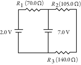
Free
(Multiple Choice)
4.7/5  (38)
(38)
Correct Answer: Verified
A
Internal battery resistance: Two light bulbs, B1 and B2, are connected to a battery having appreciable internal resistance as shown in the figure. What happens to the brightness of bulb B1 when we close the switch S? 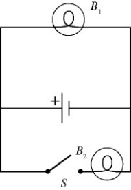
Free
(Multiple Choice)
4.8/5 (31)
Correct Answer:Verified
B
Resistors in combination: Three resistors having resistances of 4.0 Ω, 6.0 Ω, and 10.0 Ω are connected in parallel. If the combination is connected in series with an ideal 12-V battery and a 2.0-Ω resistor, what is the current through the 10.0-Ω resistor?
Free
(Multiple Choice)
4.7/5 (34)
Correct Answer:Verified
A
RC circuits: For the circuit shown in the figure, the switch S is initially open and the capacitor voltage is 80 V. The switch is then closed at time t = 0. What is the charge on the capacitor when the current in the circuit is 33 μA? 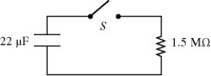
(Multiple Choice)
5.0/5 (34)
RC circuits: A 6.0-μF capacitor is connected in series with a 5.0 MΩ resistor, and this combination is connected across an ideal 15-V DC battery. What is the current in the circuit when the capacitor has reached 20% of its maximum charge?
(Multiple Choice)
4.9/5 (31)
RC circuits: An RC circuit is connected across an ideal DC voltage source through an open switch. The switch is closed at time t = 0 s. Which of the following statements regarding the circuit are correct? (There may be more than one correct choice.)
(Multiple Choice)
4.7/5 (28)
Resistors in combination: For the circuit shown in the figure, the current in the 8-Ω resistor is 0.50 A, and all quantities are accurate to 2 significant figures. What is the current in the 2-Ω resistor? 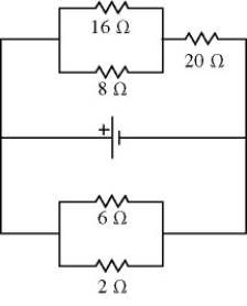
(Multiple Choice)
4.7/5 (30)
Internal battery resistance: What is the maximum current that can be drawn from a 1.50-V battery with an internal resistance of 0.30 ohm?
(Multiple Choice)
4.9/5 (34)
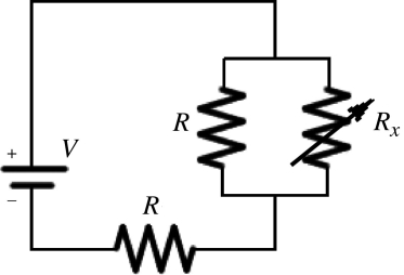
Resistors in combination: Two identical resistors of resistance R = 24 Ω and a variable resistor Rx are connected to an ideal battery of voltage V as shown in the figure. What should be the value of the variable resistance Rx to make the voltage across the two parallel resistors equal to  .
. 
(Multiple Choice)
4.8/5 (35)
Resistors in combination: When four identical resistors are connected to an ideal battery of voltage V = 10 V as shown in the figure, the current I is equal to 0.20 A. What is the value of the resistance R of the resistors? 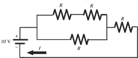
(Multiple Choice)
4.9/5 (33)
Resistors in combination: Three resistors are connected across an ideal 2.0-V DC battery as shown in the figure.
(a) At what rate does the battery supply energy to the resistors?
(b) At what rate is heat produced in the 6.0-Ω resistor? 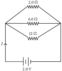
(Essay)
4.8/5 (31)
Meters: A galvanometer G has an internal resistance rg. An AMMETER is constructed by incorporating the galvanometer and an additional resistance Rs. Which one of the figures below is the most appropriate circuit diagram for the ammeter? 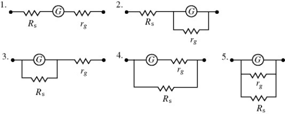
(Multiple Choice)
5.0/5 (33)
Resistors in combination: A light bulb is connected in the circuit shown in the figure with the switch S open. All the connecting leads have no appreciable resistance and the battery has no internal resistance. When we close the switch, which statements below accurately describe the behavior of the circuit? (There may be more than one correct choice.) 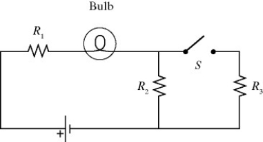
(Multiple Choice)
4.8/5 (38)
Resistors in combination: Four resistors are connected across an 8-V DC battery as shown in the figure. The current through the 9-Ω resistor is closest to 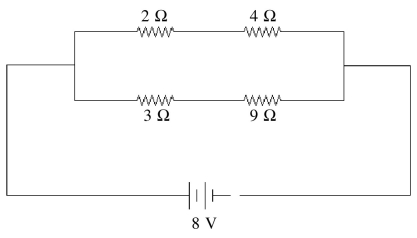
(Multiple Choice)
4.7/5 (34)
RC circuits: A 4.0-μF capacitor that is initially uncharged is connected in series with a 4.0-kΩ resistor and an ideal 17.0-V battery. How much energy is stored in the capacitor 17 ms after the battery has been connected?
(Multiple Choice)
4.8/5 (41)
Kirchhoff's rules: For the circuit shown in the figure, all quantities are accurate to 2 significant figures. What is the value of the current I1? 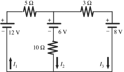
(Multiple Choice)
4.8/5 (37)
Meters: A galvanometer coil having a resistance of 20 Ω and a full-scale deflection at 1.0 mA is connected in series with a 4980 Ω resistance to build a voltmeter. What is the maximum voltage that this voltmeter can read?
(Multiple Choice)
4.9/5 (43)
Resistors in combination: Thirteen resistors are connected across points A and B as shown in the figure. If all the resistors are accurate to 2 significant figures, what is the equivalent resistance between points A and B? 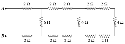
(Multiple Choice)
4.8/5 (29)
Resistors in combination: A resistor is made out of a long wire having a length L. Each end of the wire is attached to a terminal of a battery providing a constant voltage V0. A current I flows through the wire. If the wire were cut in half, making two wires of length L/2, and both wires were attached to the battery (the end of both wires attached to one terminal, and the other ends attached to the other terminal), what would be the total current flowing through the two wires?
(Multiple Choice)
4.7/5 (35)
Resistors in combination: Two unknown resistors are connected together. When they are connected in series their equivalent resistance is 15 Ω. When they are connected in parallel, their equivalent resistance is 3.3 Ω. What are the resistances of these resistors?
(Short Answer)
4.9/5 (30)
Filters
- Essay(0)
- Multiple Choice(0)
- Short Answer(0)
- True False(0)
- Matching(0)