Exam 22: Gausss Law
Exam 2: Motion Along a Straight Line55 Questions
Exam 3: Motion in Two or Three Dimensions59 Questions
Exam 4: Newtons Laws of Motion50 Questions
Exam 5: Applying Newtons Laws139 Questions
Exam 6: Work and Kinetic Energy109 Questions
Exam 7: Potential Energy and Energy Conservation50 Questions
Exam 8: Momentum, Impulse, and Collisions99 Questions
Exam 9: Rotation of Rigid Bodies26 Questions
Exam 10: Dynamics of Rotational Motion49 Questions
Exam 11: Equilibrium and Elasticity50 Questions
Exam 12: Fluid Mechanics54 Questions
Exam 13: Gravitation52 Questions
Exam 14: Periodic Motion109 Questions
Exam 15: Mechanical Waves50 Questions
Exam 16: Sound and Hearing121 Questions
Exam 17: Temperature and Heat60 Questions
Exam 18: Thermal Properties of Matter41 Questions
Exam 19: The First Law of Thermodynamics55 Questions
Exam 20: The Second Law of Thermodynamics52 Questions
Exam 21: Electric Charge and Electric Field54 Questions
Exam 22: Gausss Law54 Questions
Exam 23: Electric Potential88 Questions
Exam 24: Capacitance and Dielectrics70 Questions
Exam 25: Current, Resistance, and Electromotive Force44 Questions
Exam 26: Direct-Current Circuits51 Questions
Exam 27: Magnetic Field and Magnetic Forces105 Questions
Exam 28: Sources of Magnetic Field82 Questions
Exam 29: Electromagnetic Induction51 Questions
Exam 30: Inductance88 Questions
Exam 31: Alternating Current51 Questions
Exam 32: Electromagnetic Waves Optics53 Questions
Exam 33: The Nature and Propagation of Light31 Questions
Exam 34: Geometric Optics89 Questions
Exam 35: Interference59 Questions
Select questions type
Kirchhoff's rules: A multiloop circuit is shown in the figure. Some circuit quantities are not labeled. It is not necessary to solve the entire circuit. The emf ε is closest to 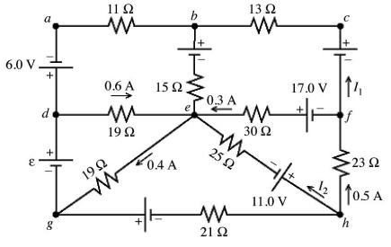
(Multiple Choice)
4.9/5  (24)
(24)
RC circuits: A 4.0-mF capacitor is discharged through a 4.0-kΩ resistor. How long will it take for the capacitor to lose half its initial stored energy?
(Multiple Choice)
4.8/5 (37)
Kirchhoff's rules: Consider the circuit shown in the figure. Note that two currents are shown. Calculate the emfs ε1 and ε3. 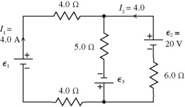
(Essay)
4.9/5 (40)
RC circuits: An uncharged 30.0-µF capacitor is connected in series with a 25.0-Ω resistor, a DC battery, and an open switch. The battery has an internal resistance of 10.0 Ω and the open-circuit voltage across its terminals is 50.0 V. The leads have no appreciable resistance. At time t = 0, the switch is suddenly closed.
(a) What is the maximum current through the 25.0-Ω resistor and when does it occur (immediately after closing the switch or after the switch has been closed for a long time)?
(b) What is the maximum charge that the capacitor receives?
(c) When the current in the circuit is 0.850 A, how much charge is on the plates of the capacitor?
(Essay)
4.8/5 (39)
RC circuits: For the circuit shown in the figure, the switch S is initially open and the capacitor voltage is 80 V. The switch is then closed at time t = 0. How long after closing the switch will the current in the resistor be 7.0 µA? 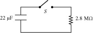
(Multiple Choice)
4.9/5 (35)
Meters: A galvanometer G has an internal resistance rg. A VOLTMETER is constructed by incorporating the galvanometer and an additional resistance Rs. Which one of the figures below is the most appropriate circuit diagram for the voltmeter? 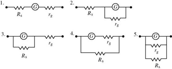
(Multiple Choice)
4.7/5 (34)
Resistors in combination: In the circuit shown in the figure, all the lightbulbs are identical. Which of the following is the correct ranking of the brightness of the bulbs? 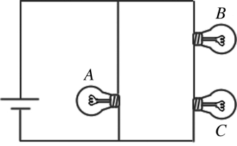
(Multiple Choice)
4.7/5 (33)
Resistors in combination: For the circuit shown in the figure, all quantities are accurate to 3 significant figures. What is the power dissipated in the 2-Ω resistor? 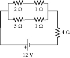
(Multiple Choice)
4.9/5 (33)
Kirchhoff's rules: For the circuit shown in the figure, determine the current in
(a) the 7.0-Ω resistor.
(b) the 8.0-Ω resistor.
(c) the 4.0-Ω resistor. 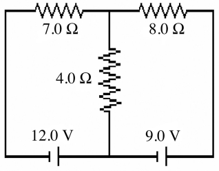
(Essay)
4.8/5 (32)
Meters: A galvanometer with a resistance of 40.0 Ω deflects full scale at a current of 2.0 mA. What resistance should be used with this galvanometer in order to construct a voltmeter that can read a maximum of 50 V?
(Multiple Choice)
4.8/5 (42)
Resistors in combination: In the circuit shown in the figure, an ideal ohmmeter is connected across ab with the switch S open. All the connecting leads have negligible resistance. The reading of the ohmmeter will be closest to 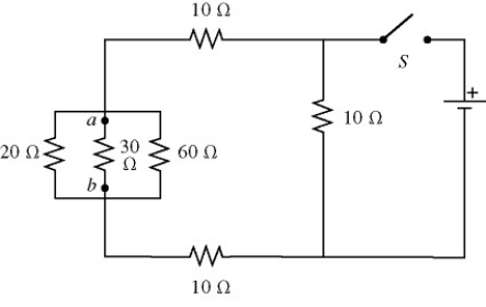
(Multiple Choice)
4.8/5 (34)
Internal battery resistance: When a 100-Ω resistor is connected across the terminals of a battery of emf ε and internal resistance r, the battery delivers 0.794 W of power to the 100-Ω resistor. When the 100-Ω resistor is replaced by a 200-Ω resistor, the battery delivers 0.401 W of power to the 200-Ω resistor. What are the emf and internal resistance of the battery?
(Multiple Choice)
4.8/5 (37)
Kirchhoff's rules: A multiloop circuit is shown in the figure. It is not necessary to solve the entire circuit. The current I2 is closest to 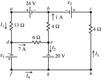
(Multiple Choice)
4.8/5 (34)
Resistors in combination: The figure shows three identical lightbulbs connected to a battery having a constant voltage across its terminals. What happens to the brightness of lightbulb 1 when the switch S is closed? 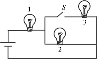
(Multiple Choice)
4.8/5 (37)
Meters: In the circuit shown in the figure, two 360.0-Ω resistors are connected in series with an ideal source of emf. A voltmeter with internal resistance of 6350 Ω is connected across one of the resistors and reads 3.23 V. Find the emf of the source. 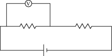
(Short Answer)
4.8/5 (36)
Resistors in combination: A 5.0-Ω resistor and a 9.0-Ω resistor are connected in parallel. A 4.0-Ω resistor is then connected in series with this parallel combination. An ideal 6.0-V battery is then connected across the series-parallel combination of the three resistors. What is the current through
(a) the 4.0-Ω resistor?
(b) the 5.0-Ω resistor?
(c) the 9.0-Ω resistor?
(Essay)
4.9/5 (45)
Resistors in combination: A 4.00-Ω resistor, an 8.00-Ω resistor, and a 24.0-Ω resistor are connected together.
(a) What is the maximum resistance that can be produced using all three resistors?
(b) What is the minimum resistance that can be produced using all three resistors?
(c) How would you connect these three resistors to obtain a resistance of 10.0 Ω?
(d) How would you connect these three resistors to obtain a resistance of 8.00 Ω?
(Essay)
4.9/5 (44)
Internal battery resistance: When a 20.0-ohm resistor is connected across the terminals of a 12.0-V battery, the voltage across the terminals of the battery falls by 0.300 V. What is the internal resistance of this battery?
(Multiple Choice)
4.9/5 (42)
RC circuits: For the circuit shown in the figure, the capacitors are all initially uncharged, the connecting leads have no resistance, the battery has no appreciable internal resistance, and the switch S is originally open. 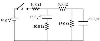 (a) Just after closing the switch S, what is the current in the 15.0-Ω resistor?
A) 0.00 A
B) 1.67 A
C) 2.50 A
D) 3.33 A
E) 5.00 A
(b) After the switch S has been closed for a very long time, what is the potential difference across the 28.0-μF capacitor?
A) 0.00 V
B) 25.0 V
C) 3.33 V
D) 37.5 V
E) 50.0 V
(a) Just after closing the switch S, what is the current in the 15.0-Ω resistor?
A) 0.00 A
B) 1.67 A
C) 2.50 A
D) 3.33 A
E) 5.00 A
(b) After the switch S has been closed for a very long time, what is the potential difference across the 28.0-μF capacitor?
A) 0.00 V
B) 25.0 V
C) 3.33 V
D) 37.5 V
E) 50.0 V
(Essay)
4.8/5 (42)
RC circuits: An uncharged 1.0-μF capacitor is connected in series with a  resistor, an ideal
  battery, and an open switch. What is the voltage across the capacitor
  after closing the switch?
(Multiple Choice)
4.8/5 (37)
Filters
- Essay(0)
- Multiple Choice(0)
- Short Answer(0)
- True False(0)
- Matching(0)